
Integra RS Coupe L4-1834cc 1.8L DOHC MFI (1998)
General Module: Diagram Information and Instructions
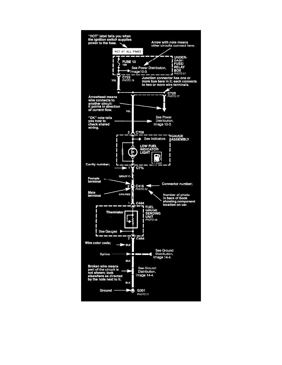
Circuit Schematics
Each schematic represents one circuit. A circuit's wires and components are arranged to show current flow, from power at the top of the page, to ground,
at the bottom.
Other circuits may share power or ground terminals or wiring with the circuit shown. A wire that connects one circuit to another, for example, is cut short
and has an arrowhead at the end of it pointing in the direction of current flow. Next to the arrowhead is the name of the circuit or component which
shares that wiring. To quickly check shared wiring, check the operation of a component it serves. If that component works, you know the shared wiring is
OK.
All connectors are numbered (C709, C416, etc.). Below each connector number (except those for components) is the number of a photo showing the