
TL L5-2451cc 2.5L SOHC MFI (1997)
car. The VIEW number refers to an illustration that shows the connector face, wire colors, connector cavity numbers, and other details.
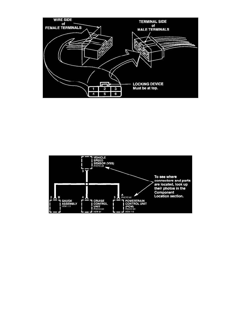
Cavity Numbering System
The connector cavity numbering sequence begins at the top left corner of the connector as seen from either of the view points. Disregard any
numbers moulded into the connector housing.
Wires
Wires are identified by the abbreviated names of their colors; the second color is the color of the stripe. Wires are also identified by their location
in a connector. The number "2" next to the male and female wire terminals at C416, for example, means those terminals join in cavity 2 of
connector C416.
Locating Components and Connectors
Component Locations
To see where a component or connector is located on the car, look up its photo number in the Component Location section. The photo will also
tell you the color of the connector, and how many cavities it has.