| –
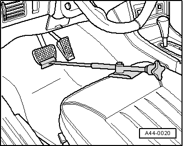
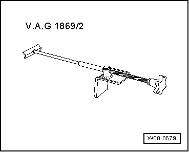
| Insert brake pedal actuator -V.A.G 1869/2- between brake pedal and driver's seat. Depress brake pedal by at least 60 mm. |
| –
| Connect hose of bleeder bottle to bleeder screws of front left and rear left brake calipers. |

Note | This will release the pressure in the hydraulic unit. |
| –
| Close bleeder screws (front left and rear left). |
| –
| Do not remove brake pedal actuator -V.A.G 1869/2-. |
| –
| As protection against escaping brake fluid, place a sufficient number of lint-free cloths in area beneath control unit and hydraulic unit. |
| –
| Unclip brake lines from bracket on plenum chamber partition panel. |
| –
| Unscrew all brake lines from hydraulic unit. |

WARNING | Do not bend the brake lines in the vicinity of the hydraulic unit. |
|
| –
| Seal brake lines and threaded holes using sealing plugs from repair kit. |
| –
| Release electrical connector and unplug connector from control unit. |
Note | t
| Make sure brake fluid does not get into connector housing of control unit. This can result in corrosion of the contacts and failure of the system. |
| t
| Use compressed air to carefully clean connector housing if necessary. |
| –
| Slacken nuts on rubber buffers on bracket for hydraulic unit. |
| –
| Detach hydraulic unit together with control unit from bracket and rubber buffers and remove from vehicle. |
| Installation is performed in reverse sequence; note the following: |
Note | t
| Do not remove sealing plugs from new hydraulic unit until corresponding brake line is ready to be fitted. |
| t
| If sealing plugs are removed from hydraulic unit sooner, brake fluid may escape and it may no longer be possible to fill and bleed the unit properly. |
| –
| Attach bracket to hydraulic unit. |
| –
| Insert hydraulic unit together with control unit in rubber buffers on bracket in vehicle. |
Note | To facilitate installation, moisten the rubber mountings in the bracket slightly with water. |
| –
| Tighten nuts on rubber buffers on bracket for hydraulic unit. |
| –
| Remove sealing plugs from new hydraulic unit. |
Note | To facilitate installation, first insert all the brake lines in the hydraulic unit and then tighten the brake line connections. |
| –
| Insert all brake lines. |
| –
| Secure all brake line connections. |
Note | Final control diagnosis can be used to establish whether line connections have been interchanged. |
| –
| Clip brake lines into bracket on plenum chamber partition panel. |
| –
| Remove brake pedal actuator -V.A.G 1869/2-. |
| –
| If the control unit is being renewed, the corresponding routine must be started on the vehicle diagnostic, testing and information system -VAS 505 x- in the Guided Functions. |
| –
| After attaching brake lines to hydraulic unit, perform final control diagnosis with Vehicle diagnostic, testing and information system -VAS 505 x-, Guided Functions. |
|
|
|

 Caution