audi Workshop Repair Guides

Audi Workshop Service and Repair Manuals

Measures to be taken if readout does not match specification > < Fault Finding if temperature increases downstream of evaporator
Checking air conditioner cooling output - vehicles with automatically controlled air conditioner
Test requirements
l  Ambient temperature above 15 °C
l  Radiator and condenser clean (clean if necessary)
l  Air conditioner compressor poly V-belt properly fitted
l  Air conditioner compressor actually being driven via poly V-belt and pulley
l  All air ducts, covers and seals OK and properly installed
l  Air flow through dust and pollen filter not impaired by dirt → Chapter „Removing and installing dust and pollen filter“
l  Air intake (in fresh-air and air recirculation mode) not impeded by contamination or retrofitted components
l  Vehicle not exposed to sunlight
l  Engine warm
l  Event recorder of operating unit, Climatronic control unit -J255- interrogated and erased, basic setting performed in „Guided fault-finding“ function → Vehicle diagnostic tester
l  Encoding and adaption of operating unit, Climatronic control unit -J255- checked in „Guided fault-finding“ function → Vehicle diagnostic tester
   
–  Switch on the ignition and make the following settings on the operating unit, Climatronic control unit -J255-:
l  „Auto“ mode - lamp in AUTO button lights.
l  Set the rotary temperature control -1- to the „Cold“ stop.
l  Set the rotary air distribution control -5- to „Dash panel vents“.
l  Air conditioner compressor on - lamp in AC button -6- lights.
–  Start the engine and check the following functions:
l  Operation of radiator fan -V7- (and -V177-) (actuation and speed governed by pressure in refrigerant circuit and engine temperature).
  Note
t  Depending on the version of the operating unit, Climatronic control unit -J255-, the radiator fan -V7- (and -V177-) are only switched in as of a certain pressure in the refrigerant circuit (currently as of a pressure of approx. 9 bar). To check actuation of the radiator fans, „read measured values“ in the air conditioner „Guided fault-finding“ function → Vehicle diagnostic tester.
t  If one of these test requirements is not satisfied, interrogate the event recorder, perform final control diagnosis and read out the measured values of the operating unit, Climatronic control unit -J255- in the „Guided fault-finding“ function → Vehicle diagnostic tester.
t  Depending on the vehicle model, a radiator fan 2 -V177- may also be fitted → Rep. gr.19.
l  Operation of fresh air blower -V2- at maximum speed
  A87-10557
l  Switching of the air conditioner to air recirculation mode (approx. 1 minute after starting the vehicle, the air flow/fresh-air flaps are closed and the air recirculation flap -1- opened, air is drawn in by the fresh air blower -V2- from the passenger compartment behind the glove compartment)
Checking
–  Measure the ambient temperature - must be above 15 °C.
–  Close the front lid, doors and windows.
–  Open all dash panel vents.
  A87-10863
–  To switch off the air conditioner at the operating unit, Climatronic control unit -J255-, press the AC button -6-.
l  The lamp in the AC button does not light.
–  „Read measured values“ in air conditioner „Guided fault-finding“ function → Vehicle diagnostic tester.
–  Check the display in the display zones:
l  The air conditioner compressor is deactivated, the display is 0 A (amps).
l  At the measured ambient temperature, the pressure in the refrigerant circuit is equal to or higher than the value in the table.
  A87-10557
Ambient temperature in °CPressure display (in bar absolute)
154,7
205,6
256,6
307,6
358,8

  Note
t  At absolute pressure, 0 bar corresponds to an absolute vacuum. Normal ambient pressure thus corresponds to roughly 1 bar absolute. On the scales of most pressure gauges, 0 bar corresponds to an absolute pressure of 1 bar (can be seen from „-1“ mark below „0“).
t  The pressure in the refrigerant circuit is governed by the ambient temperature. Due to the radiation of heat by components (e.g. the radiator), the pressure displayed with a warm engine is slightly higher than that given for the corresponding ambient temperature.
If the displayed pressure is lower than that given in the table:
–  Check the signal of the high-pressure sender -G65- → Chapter.
–  If no fault is found at the high-pressure sender -G65-, there is not enough refrigerant in the circuit. The vehicle is to be taken to a workshop equipped with the necessary tools where the work can be performed by appropriately qualified personnel.
If the pressure in the refrigerant circuit is OK:
   
–  Switch on the air conditioner at the operating unit as follows:
  Note
Engine running
l  „Auto“ mode - lamp in AUTO button lights.
l  Set the rotary temperature control -1- to the „Cold“ stop.
l  Set the rotary air distribution control -5- to „Dash panel vents“.
l  Air conditioner compressor on - lamp in AC button -6- lights.
–  „Read measured values“ in air conditioner „Guided fault-finding“ function → Vehicle diagnostic tester.
–  Check the display in the display zones:
l  Air conditioner compressor switched on: Indication of a current greater than 0.3 A (current flowing via the air conditioner compressor regulating valve -N280-).
l  Air conditioner compressor switched on: Indication of a signal ratio greater than 30 % (actuation of the air conditioner compressor regulating valve -N280-).
l  Pressure indicated rises above value with air conditioner compressor switched off.
  Note
t  If the pressure displayed does not change and actuation of the air conditioner compressor is OK, check again as to whether the air conditioner compressor is actually being driven. If it is, there is a fault in the refrigerant circuit. Take the vehicle to a workshop which is equipped with the necessary tools and at which the work can be performed by appropriately qualified personnel (there may be problems with control of air conditioner compressor) → Air conditioner with refrigerant R134a. Inform the workshop of the problem detected.
t  The air conditioner compressor regulating valve -N280- is actuated by the operating unit, Climatronic control unit -J255- such that the temperature of the air downstream of the evaporator reaches the specified value (approx. 2 to 5 °C).
t  After starting the vehicle, a value greater than 75 % (0.55 A) is displayed for actuation of the air conditioner compressor regulating valve -N280- depending on the measured temperature, engine speed and electrical system voltage. As soon as the temperature measured by the evaporator output temperature sender -G263- approaches the specified value, actuation is cancelled and the air conditioner compressor output thus reduced.
t  Under certain operating conditions, residual moisture in the refrigerant circuit may lead to the formation of ice at the compressor regulating valve (and expansion valve). Such ice formation impedes the control of the air conditioner compressor. The evaporator is cooled down too much and ices up. An iced-up evaporator may cause various problems → Chapter.
t  If no or an insufficient current is displayed in the measured values for actuation of the air conditioner compressor regulating valve -N280-, check actuation of -N280- → Chapter.
  A87-10557
–  Press the Air recirculation button -4- on the operating unit, Climatronic control unit -J255-.
l  The „Air recirculation mode“ lamp in the button lights.
–  Set the engine speed to 2000 rpm (start of time measurement).
–  „Read measured values“ of evaporator output temperature sender -G263- in air conditioner „Guided fault-finding“ function → Vehicle diagnostic tester.
  A87-10557
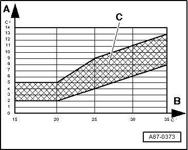
–  Compare the measured value displayed (for -G263-) to the values in the graph.
A - Air temperature measured by evaporator output temperature sender -G263-
B - Ambient temperature
C - Permissible tolerance range
Depending on ambient temperature, the measured air temperature must be within the stated tolerance range after 5 minutes.
  Note
t  If the required values are not attained, check the measured value for the evaporator output temperature sender -G263- and the centre vent temperature sender -G191- and compare the measured values displayed. When doing so, check that there is actually a flow of air to these temperature sensors (observe air distribution).
t  If the measured values in the display zones differ, perform the measures for fault finding to be taken if the readout does not match the specification → Chapter.
t  If the measured value for the evaporator output temperature sender -G263- is greater than the measured value for the centre vent temperature sender -G191-, check for proper installation of -G263- and perform the electrical checks for this sender in the „Guided fault-finding“ function → Vehicle diagnostic tester.
t  Operation of the air conditioner can be seen, for example, from the fact that the refrigerant pipe on the low-pressure end (thick pipe) cools down.
If the measured value of the evaporator output temperature sender -G263- (and thus the system cooling output) is OK:
–  Compare the measured value displayed (for the evaporator output temperature sender -G263-) to the measured value for the centre vent temperature sender -G191-. When doing so, check that there is actually a flow of air to these temperature sensors (observe air distribution).
After 5 minutes, the measured value for -G191- must not be more than 3 °C higher than the value for -G263-.
  Note
t  If the measured value in one of the two senders is OK, check actuation and operation of the temperature flap control motor -V68- → Chapter and → Chapter in the „Guided fault-finding“ function → Vehicle diagnostic tester.
t  Depending on the operating unit, Climatronic control unit -J255-, the temperature flap control motor -V68- on vehicles manufactured in 2010 may also be displayed as left temperature flap control motor -V158- → Vehicle diagnostic tester, „Guided fault-finding“ function.
t  If the measured value for the centre vent temperature sender -G191- is lower thant that for the evaporator output temperature sender -G263-, check for proper installation of -G263- and -G191- as well as checking the electrical connections for contact resistance. Replace the defective sender if necessary.
t  If no fault is found at the centre vent temperature sender -G191- and the temperature flap control motor -V68-, perform the measures to be taken in the event of temperature increase downstream of the evaporator → Chapter.
t  The temperature of the air flow from the „Centre“ dash panel vents can additionally be measured using a commercially available thermometer for example.
t  Problems relating to differences between the temperature of the air emitted from the vents with an identical setting in air conditioner control mode may be due to the following: The temperature flaps in the air distribution housing not closing completely or reaching their end position → Chapter „Removing and installing air distribution housing“ and „Guided fault-finding“ function → Vehicle diagnostic tester. Air in the heat exchanger (fluctuating flow through heat exchanger and thus uneven heat distribution) → Chapter or detachment of foam seal on installation of heat exchanger, thus allowing air to flow past the heat exchanger.
  A87-0373

Measures to be taken if readout does not match specification > < Fault Finding if temperature increases downstream of evaporator