audi Workshop Repair Guides

Audi Workshop Service and Repair Manuals

Exploded view - gearbox housing and clutch housing > < Exploded view - removing and installing input shaft, output shaft, differential, selector mechanism and selector forks
Removing and installing cover for gearbox housing, clutch housing, selector shaft with selector mechanism cover, input shaft, output shaft, differential and selector mechanism
   
Removing and installing cover for gearbox housing, clutch housing, selector shaft with selector mechanism cover, input shaft, output shaft, differential and selector mechanism
Special tools and workshop equipment required
t  Support clamp -VW 313-
t  Thrust plate -VW 401-
t  Thrust plate -VW 402-
t  Press tool -VW 412-
t  Gearbox support -3221-
t  Guide pin -T10079-

   
t  Press tool -VW 407-
t  Tube -VW 418 A-
t  Thrust plate -3074-
t  Thrust piece -T10080-
t  Thrust block -T10083-
t  Drip tray -V.A.G 1306-

   
t  Torque wrench -V.A.G 1331-
t  -2-Puller -Kukko 18/1 -
t  -3-Splitter -Kukko 17/1-
t  -1-Three-arm puller -Kukko 30/1-
t  -1-Two-arm puller -Kukko 20/10-
t  -3-Two-arm puller -Kukko 204/2-
t  Sealant -AMV 188 200 03-
t  Hexagon socket head bolt -M 8 X 15-

   
t  Hot air blower -V.A.G 1416-
  W00-0004
t  Used oil collection and extraction unit -V.A.G 1782-
  W00-10211
t  Inductive heater -VAS 6414-
Removing
l  Gearbox removed
–  Mount gearbox on assembly stand → Chapter.
–  Place used oil collection and extraction unit -V.A.G 1782- below gearbox.
–  Drain off gear oil.
  W00-10814
–  Remove clutch release lever -A- together with clutch release bearing and guide sleeve -arrows-.
–  Remove securing bolt for flange shaft (right-side) -B-.
  A34-0294
–  To do so, screw two bolts into flange and counterhold flange shaft with tyre iron or other suitable lever.
–  Pull out flange shaft together with spring, thrust washer and tapered ring.
  A34-0615
–  Unbolt gearbox housing cover -arrow- and pull off carefully.
  N34-10164
–  Pull out pivot pin -1- for 5th/6th gear selector fork -2- and remove selector fork.
  N34-10166
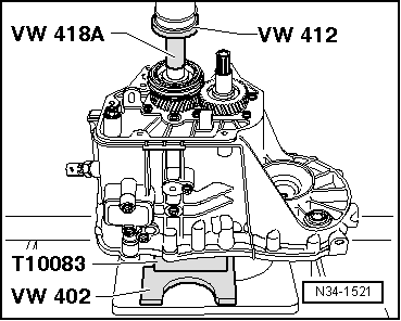
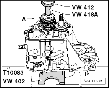
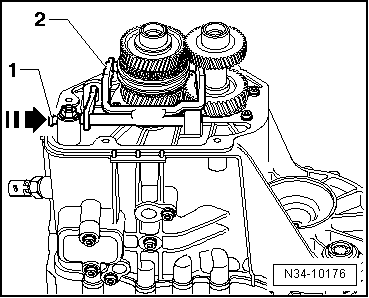
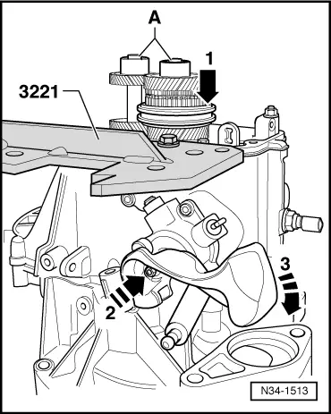
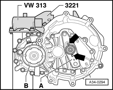
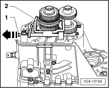
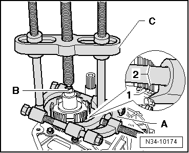
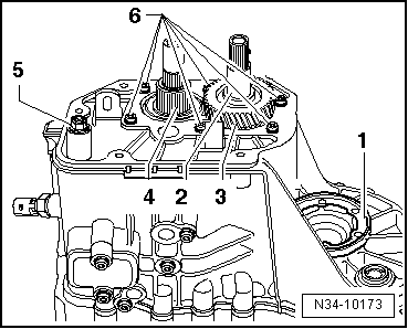
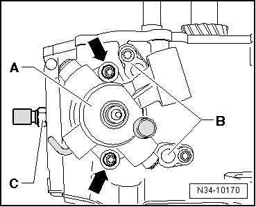
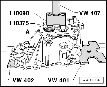
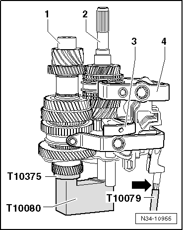
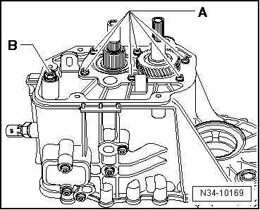
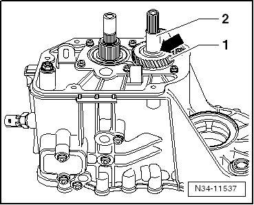
–  Remove bolts -A- for inner bearing races on input and output shafts. To do this, engage 5th gear -arrow 1- and 1st gear -arrows 2- and -3-.
–  The input and output shafts are both locked when these two gears are engaged. The two bolts can now be loosened.
  Note
t  
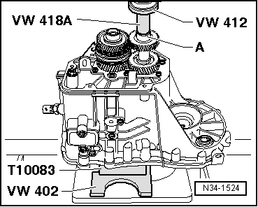
If the shafts are not being renewed, carefully clean residual locking compound out of tapped holes using a thread tap.
t  
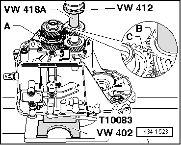
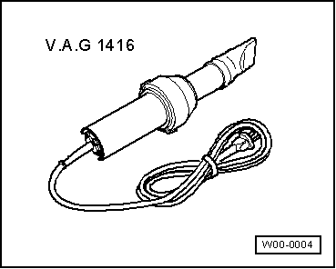
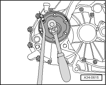
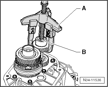
Pull off 6th gear wheel using three-arm puller -Kukko 30/1-. While doing so, heat gear wheel using hot air blower -V.A.G 1416-.
t  
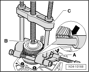
If necessary, 6th gear wheel can be pulled off part of the way using two-arm puller -Kukko 204/2- until spindle of puller reaches stop. Then remove completely using three-arm puller -Kukko 30/1-.
  N34-1513
–  Pull off 6th gear wheel and roller bearing inner race for output shaft.
A - Three-arm puller -Kukko 30/1-
B - Hexagon socket head bolt -M8 x 15-
  N34-11536
–  Clamp splitter -Kukko 17/1--A- behind the driving teeth (not the dog teeth) on the 6th speed selector gear -arrow-.
A - Splitter 12 ... 75 mm -Kukko 17/1-
B - Hexagon socket head bolt -M8 x 15-
C - Puller -Kukko 18/1-
–  Pull off 6th speed selector gear together with roller bearing inner race for input shaft.
–  Remove locking collar for 5th/6th speed gear with locking pieces.
  N34-10168
–  Clamp splitter -Kukko 17/1--A- behind 5th gear synchro-ring -1-. This will press the synchro-ring onto the synchronising hub -2-.
A - Splitter 12 ... 75 mm -Kukko 17/1-
B - Hexagon socket head bolt -M8 x 15-
C - Puller -Kukko 18/1-
–  Pull off 5th/6th gear synchronising hub with sleeve for 6th gear needle bearing and 5th gear synchro-ring.
  Note
The 5th gear synchro-ring must always be renewed after removal.
–  Remove bolt securing flange shaft (left-side). To do this, screw two bolts into flange and counterhold flange shaft with tyre iron or other suitable lever.
  N34-10174
–  Remove flange shaft (left-side) -1- with spring.
–  Detach sleeve -2- and 5th speed selector gear with needle bearing -4-.
–  Unscrew hexagon flange nut -5- for selector mechanism (reverse gear wheel mounting).
–  Unscrew securing bolts -6- for bearing mounting for input and output shafts.
If 5th gear wheel can be removed by hand:
–  Take off 5th gear wheel -3-.
If 5th gear wheel cannot be removed by hand:
–  5th gear wheel -3- is pressed off at a later stage when removing bearing mounting for grooved ball bearings → Fig..
Continued for all vehicles:
–  Turn gearbox in assembly stand so that clutch housing faces upwards.
–  Remove bolts securing gearbox housing from inside clutch housing.
–  Carefully remove clutch housing by levering alternately at the protruding webs on the housing, taking care not to damage the sealing surfaces.
–  Make sure you keep clutch housing straight to avoid damaging roller bearings and bearing seat on input and output shafts.
  N34-10173
–  Remove differential -A- from gearbox housing.
  N34-10172
–  Gearbox for vehicles with start/stop system: remove gearbox neutral position sender -G701--arrow-.
  N34-11289
–  Remove selector shaft with selector mechanism cover -A-. For this purpose, bring selector shaft into the neutral position. Then remove bolts -arrows- and pull selector shaft out of gearbox housing.
–  Remove pivot pins -B- from top of gearbox.
–  Remove reversing light switch -F4--C-.
  N34-10170
–  Remove bolt -A- for securing reverse gear shaft.
–  Remove pivot pins -B- from gearbox underside.
  Note
Do not remove cover plate -arrow- when dismantling gearbox.
  A34-0300
If 5th gear wheel could not be removed:
–  Press out input and output shafts together with 5th gear wheel -A-, bearing mounting, selector mechanism (selector forks) and reverse gear wheel.
  Note
t  Set gearbox housing down in such a way that dowel sleeves in gearbox housing do not become damaged.
t  Make sure components do not drop out when being removed (get help from a second person if necessary).
  N34-10954
If 5th gear wheel could be removed:
–  Press out input and output shafts together with bearing mounting, selector mechanism (selector forks) and reverse gear wheel.
  Note
t  Set gearbox housing down in such a way that dowel sleeves in gearbox housing do not become damaged.
t  Make sure components do not drop out when being removed (get help from a second person if necessary).
Continued for all vehicles:
–  Press input and output shafts and 5th gear wheel out of bearing mounting and grooved ball bearings → Fig..
–  Press input and output shafts out of bearing mounting and grooved ball bearings without 5th gear wheel → Fig..
Installing
  Note
t  Pressing bearing mounting with grooved ball bearings onto input and output shafts → Fig..
t  Pressing sleeve for 5th speed selector gear needle bearing onto input shaft → Fig..
  N34-1518
If 5th gear wheel is located on output shaft:
–  Place the input shaft -2- and output shaft -1- with bearing mounting/grooved ball bearings in thrust piece -T10080-.
–  Insert selector mechanism (selector forks) -4- in locking collars on shafts.
–  Fit reverse gear shaft -3- with reverse gear wheel.
–  Screw guide pin -T10079- onto threaded pin (reverse gear mounting) -arrow-.
  N34-10955
If 5th gear wheel is not located on output shaft:
–  Place the input shaft -2- and output shaft -1- with bearing mounting/grooved ball bearings in thrust piece -T10080-.
–  Insert selector mechanism (selector forks) -4- in locking collars on shafts.
–  Fit reverse gear shaft -3- with reverse gear wheel.
–  Screw guide pin -T10079- onto threaded pin (reverse gear mounting) -arrow-.
Continued for all vehicles:
  N34-1519
–  Insert assembled components into gearbox housing, running guide pin -T10079- into gearbox housing through hole for selector mechanism mounting.
–  Unscrew guide pin -T10079-.
–  Check that selector forks engage correctly in locking collars before pressing in bearing mounting.
  A34-0303
–  Carefully press in bearing mounting together with input and output shafts as far as the stop.
  A34-0304
–  Screw in bolt -A- for reverse gear shaft.
–  Install pivot pins -B- on underside of gearbox.
  A34-0300
–  Install reversing light switch -F4--C-.
–  Install pivot pins -B- on top of gearbox.
–  Set selector plates in neutral position.
–  Apply sealant -AMV 188 200 03- evenly to sealing surface of selector mechanism cover.
–  Install selector shaft with selector mechanism cover -A-. Then tighten bolts -arrows-.
  N34-10170
–  Gearbox for vehicles with start/stop system: fit gearbox neutral position sender -G701--arrow- and tighten securing bolt to specified torque → Item.
  N34-11289
–  Using new bolts -A-, secure bearing mounting for input and output shafts.
  Note
Tighten the bolts in stages to the specified torque in diagonal sequence, starting in the centre.
–  Tighten hexagon flange nut -B- for selector mechanism (selector forks).
–  Fit input and output shafts together with gearbox housing in thrust block -T10083-.
  N34-10169
Installation position of 5th gear wheel
The high collar -arrow- points away from the gearbox housing.
Fit 5th gear wheel -1- and sleeve -2- (if removed by hand earlier).
  N34-11537
Pressing on 5th gear wheel (if pressed off earlier):
–  Fit sleeve -2- (⇒ illustration above) onto 5th gear wheel.
Continued for all vehicles:
–  Install 5th speed selector gear with synchro-ring for 5th gear and needle bearing.
  N34-10957
Installation position of 5th/6th gear synchronising hub/locking collar
The high collar -arrow- points to the 5th speed gear and the gearbox housing cover.
  N34-10195
l  5th speed selector gear -item 1- with synchro-ring fitted.
–  Press on 5th/6th gear synchronising hub/locking collar using tube -VW 418 A-.
  WARNING
Wear protective gloves.
  N34-11538
–  Heat sleeve for 6th speed needle bearing to 100°C (maximum) and press on.
–  Fit 6th gear synchro-ring.
–  Install 6th speed selector gear with needle bearing.
  N34-1521
–  Heat roller bearing inner race -A- to 100°C (maximum) and press onto input shaft.
  WARNING
Wear protective gloves.
  N34-11539
Installation position of 6th gear wheel:
The higher collar faces the 5th gear wheel.
–  Set locking collar -A- for 5th/6th gear to neutral position to allow 6th speed selector gear to turn while pressing on 6th gear wheel.
  WARNING
Wear protective gloves.
–  Heat 6th gear wheel to 100°C (maximum).
–  Press on 6th gear wheel -B-, making sure that it meshes properly with 6th speed selector gear -C-.
  N34-1523
–  Heat roller bearing inner race -A- to 100°C (maximum) and press onto output shaft.
–  Insert magnet in gearbox housing.
  N34-1524
–  Install differential -A-.
–  Apply sealant -AMV 188 200 03- evenly to sealing surface.
–  Bolt clutch housing to gearbox housing.
–  Turn the gearbox in the assembly stand so that the gearbox housing faces upwards.
  A34-0298
–  Engage 2 gears -arrows 1- to -3- before tightening securing bolts -A-.
  N34-1513
–  Fit 5th/6th gear selector fork -2- and slide pivot pin -1- in onto stop in direction of -arrow-.
–  Apply sealant -AMV 188 200 03- evenly to sealing surface.
–  Bolt on gearbox housing cover.
  N34-10176
–  Install both flange shafts with springs, thrust washers and tapered rings.
–  Install clutch release lever together with release bearing and guide sleeve → Chapter.
  N34-10712

Exploded view - gearbox housing and clutch housing > < Exploded view - removing and installing input shaft, output shaft, differential, selector mechanism and selector forks