
A1
| Removing gearbox (vehicles with 2.0 ltr. TDI engine) |

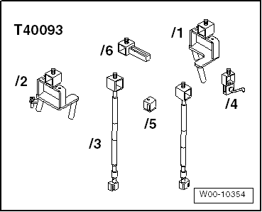
| Special tools and workshop equipment required |
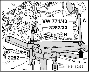
| t | Adapter -VW 771/40- |
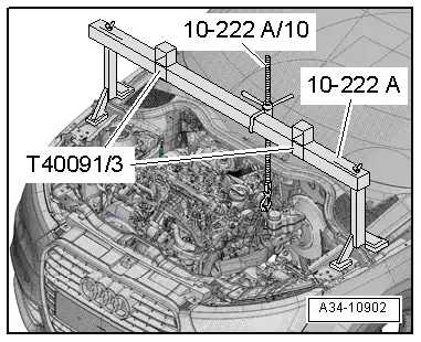
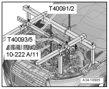
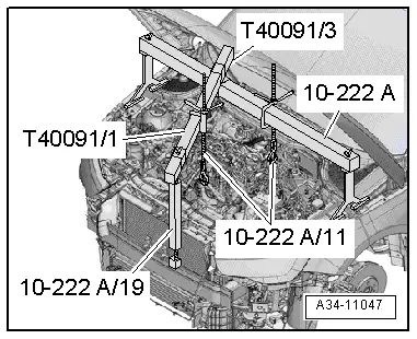
| t | Support bracket -10 - 222 A- |
| t | Hook -10 - 222 A /10- |
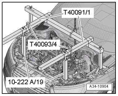
| t | Adapter -10 - 222 A /19- |
| t | Removal lever -80 - 200- |
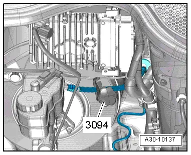
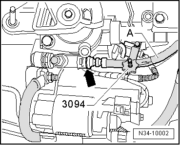
| t | Hose clamps, up to 25 mm -3094- |

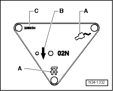
| t | Gearbox support -3282- |
| t | Pin -3282/29- |
| t | Adjustment plate -3282/33- |
| t | Engine and gearbox jack -V.A.G 1383 A- |
| t | Engine bung set -VAS 6122- |
| t | Engine support bracket, basic set -T40091- |
|
|
|
|
 Note
Note
|
|
|
|
|
|
|
|
|
|
|
|
|
|
|
|
Note
|
|
Note
|
|
Note
|
|
|
|
|
|
|
|
Note
|
|
|
|
|
|
|
|
|
|
|
|
|
|
|
|
|
|
|
|
Note |
|
|
|