audi Workshop Repair Guides

Audi Workshop Service and Repair Manuals

Installing dual clutch > < Removing dual clutch
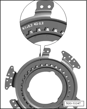
Adjusting position of engagement bearings „K 1 and K 2“
The position of the engagement bearings must be adjusted in the following cases:
t  Clutch has been renewed.
t  Engaging levers have been renewed.
t  Retainer for engaging levers has been renewed.
t  Engagement bearings have been renewed.
  Note
No adjustment is necessary if all aforementioned components have merely been removed and installed again.
Brief description
t  
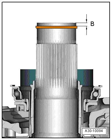
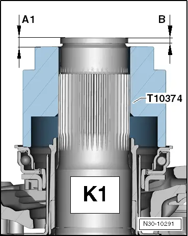
The position of the engagement bearings can be compared to the clutch play of a mechanical manual gearbox. On the 7-speed dual clutch gearbox 0AM, there are tolerances for the engagement system of the gearbox, for the gearbox itself and for the dual clutch. The tolerances must be considered separately during the adjustment procedure.
t  In the following the procedure for determining all necessary dimensions (on the gearbox) is described in order to select the required shim. In addition, the tolerances determined by the manufacturer for the clutch are given; the tolerances for the gearbox and for the clutch together determine the thickness of the shim.
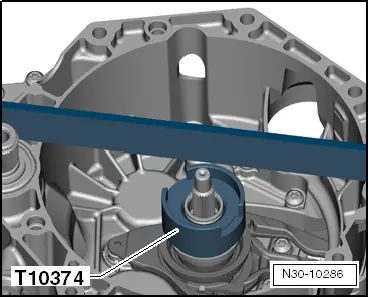
Special tools and workshop equipment required
t  
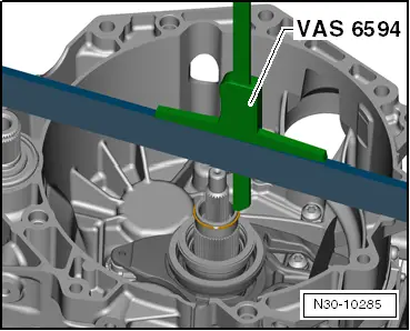
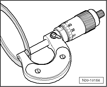
Depth gauge, digital (300 mm) -VAS 6594-
   
t  Gauge block -T10374-
  W00-10630
t  Ruler -T40100-
Procedure
l  The surface of the gearbox flange must be absolutely even to make sure the ruler lies flat on the surface.
l  Mechatronic unit for dual clutch gearbox -J743- must be installed.
  Caution
Risk of damage to the clutch and other components!
The retainer for the engaging levers and all the mechanical components of the engagement bearings must be dry and free from oil and grease.
  W00-10297
–  Insert plastic retainer for engaging levers.
  N30-10246
–  Install small engaging lever with clip.
l  Sleeve with retaining clip can only be fitted in one position.
  Note
  N30-10260
Renew bolts for small engaging lever.
–  Tighten bolts for small engaging lever.
l  Tightening torque: 8 Nm + 90°
  N30-10247
–  Insert large engaging lever.
–  Check that both engaging levers are seated correctly.
  N30-10264
–  Re-install old circlip on outer input shaft.
  N30-10277
1st step: Determining dimension „B“ for clutch „K 1 and K 2“
  A30-10094
–  Place ruler -T40100- on edge across gearbox flange above end of shaft.
  Caution
Risk of incorrect measurements.
The ruler should remain in this position during the following measurements - do not change its position or remove it.
  N30-10278
–  Apply digital depth gauge (300 mm) -VAS 6594- on top of ruler and position vertical rod of depth gauge so it is on outer input shaft.
–  Set depth gauge to „0“.
  N30-10285
–  Determine dimension „Ba“ to circlip.
l  Example: dimension „Ba“ = 2.92 mm
  N30-10279
–  Determine dimension „Bb“ to circlip on opposite side.
  Note
Do not perform measurement at gap in circlip; otherwise the circlip could be pressed out of position and the measurement would be incorrect.
l  Example: dimension „Bb“ = 3.00 mm
–  Remove and dispose of circlip.
–  Calculate mean value of dimensions „Ba“ and „Bb“.
   Formula:
Ba + Bb
2
Example:
l 
2,92 + 3,00
2
 = 2.96 mm
l  Result: dimension „B“ = 2.96 mm
  A30-10141
2nd step: Determining dimension „A1“ for shim for large engagement bearing „K 1“
  N30-10291
–  Place gauge block -T10374- on large engagement bearing; large opening must face downwards.
–  To make sure that gauge block -T10374- is seated correctly on engagement bearing, press down on gauge block and turn it.
l  The engagement bearing should turn together with the gauge block -T10374-.
  N30-10284
–  Apply digital depth gauge (300 mm) -VAS 6594- on top of ruler and position vertical rod of depth gauge so it is on outer input shaft.
l  Ruler -T40100- is positioned on edge across gearbox flange above end of shaft.
  Caution
Risk of incorrect measurements.
The ruler should remain in this position during the following measurements - do not change its position or remove it.
–  Set depth gauge to „0“.
  N30-10281
–  Determine dimension „A1a“ to gauge block -T10374- on one side.
l  Example: dimension „A1a“ = 2.61 mm
  N30-10282
–  Determine dimension „A1b“ to gauge block -T10374- on opposite side.
l  Example: dimension „A1b“ = 2.81 mm
–  Calculate mean value of dimensions „A1a“ and „A1b“.
   Formula:
A1a + A1b
2
Example:
l 
2,61 + 2,81
2
 = 2.71 mm
l  Result: dimension „A1“ = 2.71 mm
Calculating depth of engagement bearing „K 1“ of clutch 1:
  Note
Depth of engagement bearing „K 1“ of clutch 1 must now be calculated from dimensions „A1“ and „B“ as follows:
  N30-10283
 Dimension „A1“
Dimension „B“
+Exterior height of gauge block -T10374- (51.81 mm; fixed value)
=Depth of engagement bearing „K 1“ of clutch 1:

Example:
l  2.71 mm – 2.96 mm + 51.81 mm = 51.56 mm
l  Result: depth of engagement bearing „K 1“ of clutch 1 = 51.56 mm
Calculating clearance of clutch 1:
  Note
Clearance of clutch 1 must now be determined on the basis of depth of engagement bearing „K 1“ as follows:
   
 Depth of engagement bearing „K 1“ of clutch 1:
Specified depth of engagement bearing (50.08 mm; fixed value)
=Clearance of clutch 1

Example:
l  51.56 mm – 50.08 mm = 1.48 mm
l  Result: clearance of clutch 1 = 1.48 mm
   
Determining tolerance for clutch:
–  Read tolerance value for clutch off new clutch.
l  Example: tolerance for clutch as marked on clutch „K 1 = + 0.2“ (as shown in illustration)
Determining required shim thickness:
  N30-10347
 Clearance of clutch 1
–/+Tolerance for clutch
=Shim thickness required

Example:
l  1.48 mm + 0.20 mm = 1.68 mm
l  Result: shim thickness required = 1.68 mm
   
–  Measure and select required shim from shims supplied and have to hand for installation.
  N30-10156
Determined shim thickness
mm
Available shims
Thickness in mm
0.31 … 0.900.8
0.91 … 1.101.0
1.11 … 1.301.2
1.31 … 1.501.4
1.51 … 1.701.6
1.71 … 1.901.8
1.91 … 2.102.0
2.11 … 2.302.2
2.31 … 2.502.4
2.51 … 2.702.6
2.71 … 3.302.8

   
3rd step: Determining dimension „A2“ for shim for small engagement bearing „K 2“
  N30-10292
–  Only insert small engagement bearing.
  N30-10262
l  The small engagement bearing only fits in one position due to the 4 grooves.
  N30-10232
–  Check that small engagement bearing is installed correctly and grooves are seated properly by turning it -arrows-.
  N30-10261
–  Place gauge block -T10374- on small engagement bearing; large opening must face upwards.
  N30-10286
–  Apply digital depth gauge (300 mm) -VAS 6594- on top of ruler and position vertical rod of depth gauge so it is on outer input shaft.
l  Ruler -T40100- is positioned on edge across gearbox flange above end of shaft.
  Caution
Risk of incorrect measurements.
The ruler should remain in this position during the following measurements - do not change its position or remove it.
–  Set depth gauge to „0“.
  N30-10281
–  Determine dimension „A2a“ to gauge block -T10374- on one side.
l  Example: dimension „A2a“ = 2.50 mm
  N30-10288
–  Determine dimension „A2b“ to gauge block -T10374- on opposite side.
l  Example: dimension „A2b“ = 2.54 mm
–  Calculate mean value of dimensions „A2a“ and „A2b“.
   Formula:
A2a + A2b
2
Example:
l 
2,50 + 2,54
2
 = 2.52 mm
l  Result: dimension „A2“ = 2.52 mm
Determining depth of engagement bearing „K 2“ of clutch 2:
  Note
Depth of engagement bearing „K 2“ of clutch 1 must now be determined on the basis of dimensions „A2“ and „B“ as follows:
  N30-10289
 Dimension „A2“
Dimension „B“
+Interior height of gauge block -T10374- (36.20 mm; fixed value)
=Depth of engagement bearing „K 2“ of clutch 2:

Example:
l  2.52 mm – 2.96 mm + 36.20 mm = 35.76 mm
l  Result: depth of engagement bearing „K 2“ of clutch 2 = 35.76 mm
Calculating clearance of clutch 2:
  Note
Clearance of clutch 2 must now be determined on the basis of depth of engagement bearing „K 2“ as follows:
   
 Depth of engagement bearing „K 2“ of clutch 2:
Specified depth of engagement bearing (34.35 mm; fixed value)
=Clearance of clutch 2

Example:
l  35.76 mm – 34.35 mm = 1.41 mm
l  Result: clearance of clutch 2 = 1.41 mm
   
Determining tolerance for clutch:
–  Read tolerance value for clutch off new clutch.
l  Example: tolerance for clutch as marked on clutch „K 2 = + -0.2“ (as shown in illustration)
Determining required shim thickness:
  N30-10347
 Clearance of clutch 2
–/+Tolerance for clutch
=Shim thickness required

Example:
l  1.41 mm – 0.20 mm = 1.21 mm
l  Result: shim thickness required = 1.21 mm
   
–  Measure and select required shim from shims supplied and have to hand for installation.
  N30-10156
Determined shim thickness
mm
Available shims
Thickness in mm
0.31 … 0.900.8
0.91 … 1.101.0
1.11 … 1.301.2
1.31 … 1.501.4
1.51 … 1.701.6
1.71 … 1.901.8
1.91 … 2.102.0
2.11 … 2.302.2
2.31 … 2.502.4
2.51 … 2.702.6
2.71 … 3.302.8

  Caution
Risk of damage to the clutch and other components!
Fit only one shim on each engagement bearing when adjusting.
   
–  Remove and dispose of circlip on outer input shaft.
–  The clutch can be installed → Chapter.
  N30-10277

Installing dual clutch > < Removing dual clutch