audi Workshop Repair Guides

Audi Workshop Service and Repair Manuals

Charge air cooler > < Turbocharger - exploded view
Removing and installing turbocharger
Special tools and workshop equipment required
   
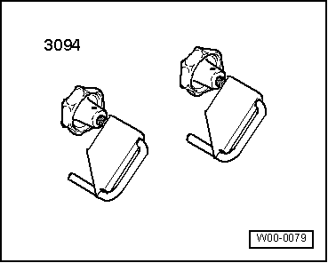
t  Hose clamps for hoses up to 25 mm -3094-
  W00-0079
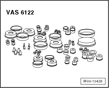
t  Engine bung set -VAS 6122-
  W00-10435
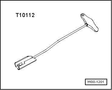
t  Puller -T10112-
Removing
  Caution
If the turbocharger has suffered mechanical damage (e.g. damaged compressor wheel), it is not sufficient merely to fit a new turbocharger. The following work must be performed in order to avoid further damage:
t  Check air cleaner housing, air filter element and air hoses for dirt and foreign particles.
t  Check the entire charge air system (including the charge air cooler) for foreign matter.
t  If foreign matter is found in the charge air system, clean all relevant ducts and hoses and renew charge air cooler if necessary.
–  Remove catalytic converter → Chapter.
  W00-1201
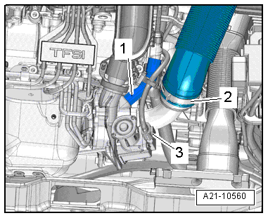
–  Disconnect crankcase breather hose -1-.
–  Release hose clip -2- and detach air hose.
–  Unplug electrical connector -3-.
  A21-10560
–  Remove bolts -1- and detach retaining bracket.
–  Unplug electrical connector -2- on charge pressure sender -G31-/intake air temperature sender 2 -G299- and move clear electrical wiring.
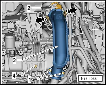
–  Release retainers -arrows- and detach air pipe -3- first from throttle valve module -J338- and then from turbocharger.
–  Fold open cover -4- and remove bolt behind it.
  N15-10561
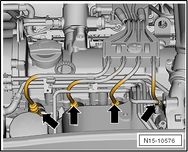
–  Pull off spark plug connectors -arrows- using puller -T10112- and move ignition cables back towards rear.
  N15-10576
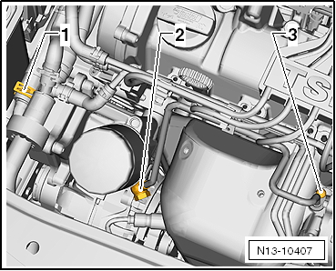
–  Remove banjo bolt -2-.
–  Remove bolt -3- and detach oil supply pipe.
  Note
Disregard -item 1-.
  N13-10407
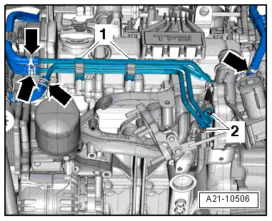
–  Clamp off coolant hoses using hose clamps up to 25 mm -3094-, release hose clips -arrows- and disconnect hoses.
–  Unscrew bolts -1 and 2- and detach coolant pipes.
  A21-10506
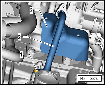
–  Unscrew bolt -1- and pull oil return pipe -2- out of turbocharger.
–  Unscrew bolt for heat shield -3- and detach heat shield.
  N21-10276
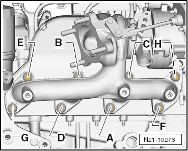
–  Slacken nuts in the sequence: -H … A-.
–  Remove nuts and detach turbocharger with exhaust manifold.
–  Seal off open pipes/lines and connections with clean plugs from engine bung set -VAS 6122-.
Installing
Installation is carried out in the reverse order; note the following:
Tightening torques
l  → Chapter „Oil filter bracket and engine oil cooler - exploded view“.
l  → Chapter „Turbocharger - exploded view“.
l  → Chapter „Charge air cooler - exploded view“.
  Note
t  Renew seals, gaskets, O-rings and self-locking nuts.
t  Fill turbocharger with engine oil at connection for oil supply pipe.
t  Hose connections and hoses for charge air system must be free of oil and grease before assembly.
t  Secure all hose connections with the correct type of hose clips (same as original equipment) → Electronic parts catalogue.
t  To ensure that the air hoses can be properly secured at their connections, spray rust remover onto the worm thread of used hose clips before installing.
t  After installing the turbocharger, allow the engine to idle for approx. 1 minute without pressing the accelerator to ensure that the turbocharger is supplied with oil.
–  Install catalytic converter → Chapter.
–  Install spark plug connectors → Rep. gr.28.
–  Check oil level → Booklet808.
–  Check coolant level → Anchor.
  N21-10278

Charge air cooler > < Turbocharger - exploded view