
A1
| Pistons and conrods - exploded view |

| 1 - | Bolts |
| q | Renew |
| q | Lubricate threads and contact surface |
| q | 30 Nm + turn 90° further |
| 2 - | Conrod bearing cap |
| q | Mark cylinder allocation before removing -A- |
| q | Installation position: marking -B- faces towards pulley end (apply marking before removal if no marking is visible) |
| 3 - | Bearing shells |
| q | Upper bearing shell with oil hole for piston pin lubrication |
| q | Installation position → Fig. |
| q | Renew used bearing shells |
| 4 - | Conrod |
| q | Only renew as a complete set |
| q | Mark cylinder allocation before removing -A- |
| q | Installation position: marking -B- faces towards pulley end (apply marking before removal if no marking is visible) |
| q | Guided axially via piston |
| q | Measuring radial clearance → Chapter |
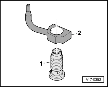
| 5 - | Piston pin |
| q | If difficult to remove, heat piston to 60 °C |
| q | Remove and install using drift -VW 222 A- |
| 6 - | Circlip |
| q | Renew |
| 7 - | Piston |
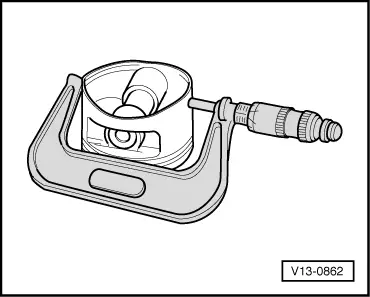
| q | Checking → Fig. |
| q | Mark installation position and cylinder number |
| q | Installation position: arrow on piston crown points to pulley end |
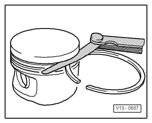
| q | Install using piston ring clamp |
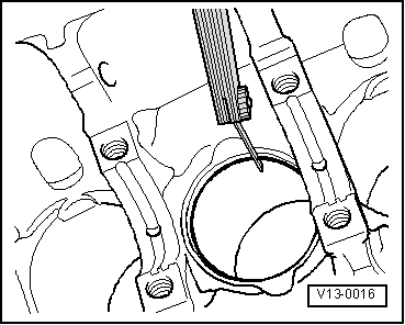
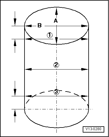
| q | Measuring cylinder bore → Fig. |
| q | Piston and cylinder dimensions → Chapter |
| 8 - | Compression ring |
| q | Pay attention to cross section |
| q | Offset gap by 120° to next compression ring |
| q | Use piston ring pliers to remove and install |
| q | Inscription „TOP“ faces towards piston crown |
| q | Measuring ring gap → Fig. |
| q | Measuring ring-to-groove clearance → Fig. |
| 9 - | Compression ring |
| q | Pay attention to cross section |
| q | Offset gap 120° relative to adjacent oil scraper ring |
| q | Use piston ring pliers to remove and install |
| q | Inscription „TOP“ faces towards piston crown |
| q | Measuring ring gap → Fig. |
| q | Measuring ring-to-groove clearance → Fig. |
| 10 - | Oil scraper ring |
| q | 3 parts |
| q | Offset gap of top steel element of piston ring by 120° to next compression ring |
| q | Offset gaps of individual parts of oil scraper ring |
| q | Measuring ring gap → Fig. |
| q | Ring-to-groove clearance cannot be checked |
| Piston ring | new mm | Wear limit mm |
| 1st compression ring | 0.20 … 0.40 | 1.00 |
| 2nd compression ring | 0.40 … 0.60 | 1.00 |
| Oil scraper ring | 0.20 … 0.80 | No wear limit data available |
|
|
| Piston ring | new mm | Wear limit mm |
| 1st compression ring | 0.04 … 0.08 | 0.15 |
| 2nd compression ring | 0.02 … 0.06 | 0.15 |
| Oil scraper ring | Cannot be measured | |
|
|
 Note
Note
|
|
|
|
|
|
 Caution