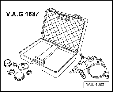
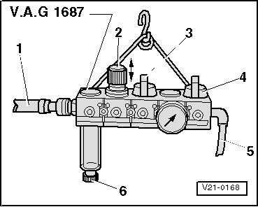
| Prepare charge air system tester -V.A.G 1687- as follows: |
| –
| Unscrew pressure control valve -2- completely and close valves -3- and -4-. |
| l
| Make sure knob is pulled out before turning pressure control valve. |
| –
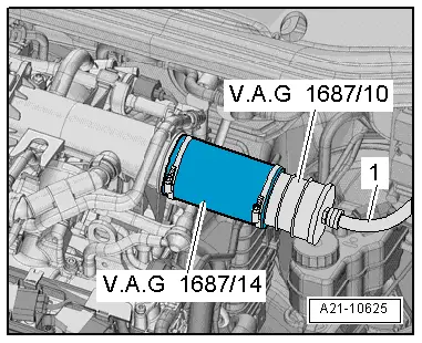
| Using a commercially available connection piece, connect charge air system tester -V.A.G 1687- to compressed air -1-. |

Note | If there is water in sight glass, remove drain plug -6- and drain water. |

Caution | Risk of damage if pressure is set too high. |
| The pressure must not exceed 0.5 bar. |
|
| –
| Adjust pressure to 0.5 bar via pressure control valve -2-. |
| –
| Open valve -4- and wait until test system is pressurised. If necessary, adjust pressure to 0.5 bar again. |
| –
| Check charge air system for audible leaks or leaks that can be felt with the hand; apply commercially available leak detecting spray or use ultrasonic tester -V.A.G 1842-. |
Note | t
| A small amount of air escapes through the valves and enters the engine. Therefore it is not possible to perform a pressure retention test. |
| t
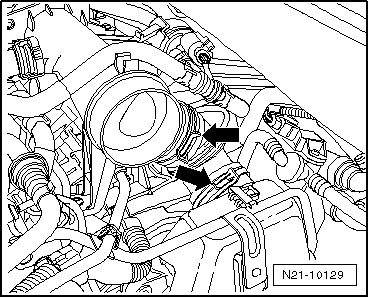
| Release pressure in test circuit by detaching hose coupling from adapter before removing adapter. |
| –
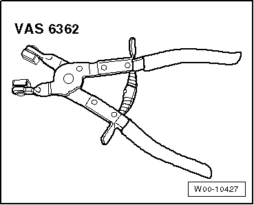
| Install air hoses with screw-type clips → Fig.. |
|
|
|