
A1
| Component | Nm | ||
| Bolts/nuts | M6 | 9 | |
| M7 | 15 | ||
| M8 | 20 | ||
| M10 | 40 | ||
| M12 | 65 | ||
| Except for the following: | |||
| Drive shaft heat shield to cylinder block | 35 | ||
|
|
|
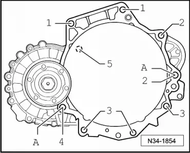
| Item | Bolt | Nm | ||||
| 1 | M12x55 | 80 | ||||
| 2 1) | M12x150 | 80 | ||||
| 3 | M10x50 | 40 | ||||
| 4 | M12x60 | 80 | ||||
| 5 2) | M6x8 | 10 | ||||
| A | Dowel sleeves for centralising | |||||
| ||||||
|
|
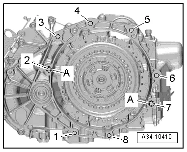
| Item | Bolt | Nm |
| 1, 8 | M10x50 | 40 |
| 2, 6, 7 | M12x65 | 80 |
| 3, 4, 5 | M12x55 | 80 |
| A | Dowel sleeves for centralising | |
 Note
Note
|
|
|
|
|
|
|
Note
|
|
 Caution