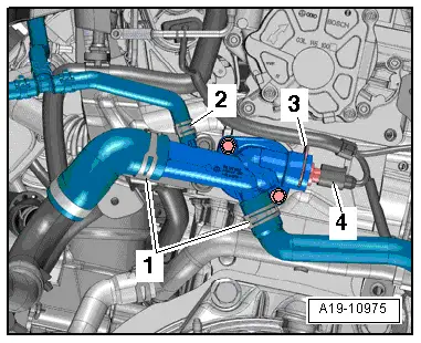
| Vehicles with thermostat: |
| –
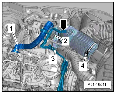
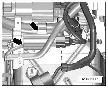
| Remove electrical connector -2- for Hall sender -G40- from bracket and unplug connector. |
| –
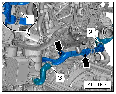
| Detach bracket from coolant pipe (front). |
| –
| Release hose clips -1- and -3- and detach coolant hoses. |
| –
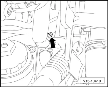
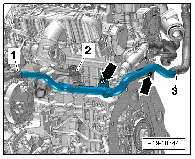
| Remove bolts -arrows- and detach coolant pipe (front) from left side of cylinder block. |
| Installation is carried out in the reverse order; note the following: |

Note | t
| Renew gaskets, seals and O-rings. |
| –
| Clean and smoothen sealing surface for O-ring. |
| –
| Lightly lubricate O-ring with coolant and slide O-ring onto coolant pipe (front). |
| –
| Push coolant pipe (front) into cylinder block. |
| –
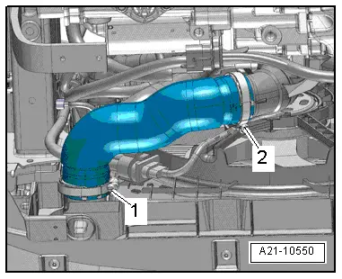
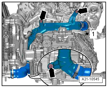
| Install air hoses with screw-type clips → Fig.. |
| –
| Install air pipe with connection → Chapter. |
| –
| Install oil filter bracket with engine oil cooler → Chapter. |
|
|
|