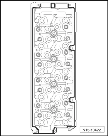
audi Workshop Repair Guides

Audi Workshop Service and Repair Manuals

Checking hydraulic valve compensation elements > < Renewing camshaft oil seal
Removing and installing camshafts
   
Removing and installing camshafts
t  Counterhold tool -T10051-
t  Puller -T10052-
t  Camshaft fitting tool -T40094-
t  Camshaft fitting tool -T40095-
t  Clamping tool -T40096/1- for vehicles with two-piece camshaft gear
t  Electric drill with plastic brush attachment
t  Safety goggles
t  Sealant → Electronic parts catalogue

   
Removing
l  Cylinder head installed.
–  Remove engine cover panel -arrows-.
–  Take toothed belt off camshaft sprocket and high-pressure pump sprocket → Chapter „Removing and installing toothed belt“.
–  Remove cylinder head cover → Chapter.
  A10-11183
–  Remove bolts -1- and detach camshaft sprocket.
  N15-10498
–  Counterhold using counterhold tool -T10051- and loosen bolt -1- for camshaft hub.
–  Unscrew bolt approx. 2 turns.
  N15-0271
–  Apply puller -T10052- to camshaft hub and and screw bolts -1- into hub.
–  Counterhold on hexagon flats (30 mm) of puller and screw in bolt -2- to pull off camshaft hub.
–  Detach hub from taper of camshaft.
–  Remove vacuum pump → Rep. gr.47.
  N15-0280
–  Slacken retaining frame bolts in the sequence -24 ... 1-.
–  Remove bolts and carefully release retaining frame from bonded joint.
–  Mark fitting location of camshafts for re-installation and remove.
Installing
l  Tightening torques → Chapter „Valve gear - exploded view“
  Caution
Make sure axial bearings in retaining frame are not damaged.
The camshafts MUST be installed using the camshaft fitting tool -T40094- as described in the following.
  N15-10483
  Caution
Protect lubrication system and bearings against contamination.
Cover exposed parts of the engine.
  WARNING
Protect eyes against injuries.
Wear safety goggles.
–  Remove remaining sealant from cylinder head and retaining frame using rotating plastic brush or similar.
–  Clean sealing surfaces; they must be free of oil and grease.
–  Oil running surfaces of both camshafts.
  A17-0097
Set up camshaft fitting tool -T40094- as follows:
–  Secure supports -T40094/9- and -T40094/10- (with -T40094/11-) to base plate, as shown in illustration. If necessary, remove any supports already attached at these positions.
  A15-10509
–  Fit support -T40094/1- onto position -F- and support -T40094/2- onto position -A-.
  A15-10510
–  Place inlet camshaft in supports -T40094/1- and -T40094/2-.
–  Turn inlet camshaft in such a way that it can be locked in „TDC“ position using locking device -arrow 1-.
l  Recess -arrow 2- for cylinder head bolt must face outwards.
  A15-10511
–  Place exhaust camshaft in supports -T40094/9- and -T40094/10-.
–  Lock exhaust camshaft with top section -T40094/11-.
l  The lug -1- on the top section must engage in the slot -2- in the camshaft,
Vehicles with two-piece camshaft gear:
–  Place clamping tool -T40096/1- on teeth of exhaust camshaft in such a way that the two arms of the tool engage on the two halves of the gear (one in each half, as shown in illustration).
l  The wider arm must engage in the wider half of the gear.
–  Tighten the clamping tool using the knurled wheel so that the faces of the gear teeth are in alignment.
All vehicles (continued):
–  Slide inlet camshaft towards exhaust camshaft, until gear teeth engage -arrows-.
  A15-10512
–  Fit retaining frame -1- on camshafts.
l  All camshaft bearings must be seated on the camshafts.
–  Position camshaft fitting tool -T40095- and fix camshafts in position in retaining frame, as shown in illustration.
–  Detach top section -T40094/11-.
  Note
  A15-10154
Note the use-by date of the sealant.
–  Cut off nozzle of tube at front marking (nozzle Ø approx. 2 mm).
  A17-0081
  Caution
Make sure excess sealant does not contaminate camshaft bearings.
The beads of sealant must not be thicker than specified.
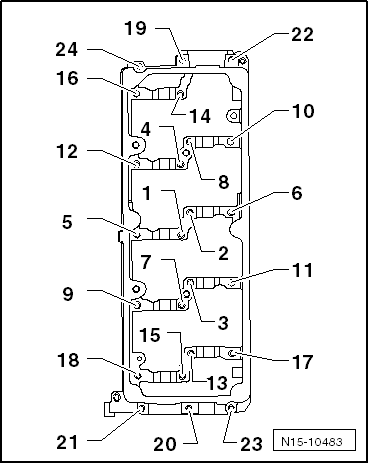
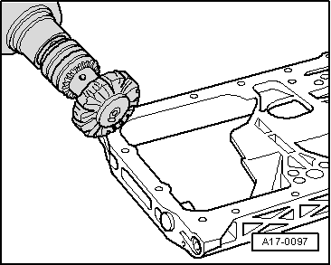
–  Apply beads of sealant onto clean sealing surfaces of cylinder head as shown in illustration.
l  
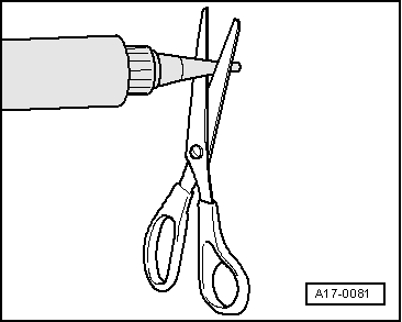
Thickness of sealant beads: 2 ... 3 mm.
  Note
t  The retaining frame should be fitted and secured without delay, as the sealant starts hardening immediately.
t  After installing the retaining frame, wait about 30 minutes for the sealant to dry.
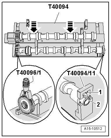
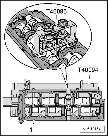
–  Take camshafts together with retaining frame, camshaft fitting tool -T40095- and, if necessary, clamping tool -T40096/1- out of camshaft fitting tool -T40094- and insert components carefully into cylinder head.
  N15-10422
–  Screw in retaining frame bolts in the sequence -1 ... 24- evenly by hand until they make contact.
l  The retaining frame should make contact with the cylinder head over the full surface.
–  Tighten bolts → Fig..
–  Remove camshaft fitting tool -T40095- and, if necessary, clamping tool -T40096/1-.
Remaining installation steps are carried out in reverse sequence; note the following:
–  Install camshaft oil seal → Chapter.
–  Drive new sealing cap → Item into cylinder head to a depth of approx. 1 ... 2 mm using suitable thrust piece.
–  Install toothed belt (adjust valve timing) → Anchor.
–  Install vacuum pump → Rep. gr.47.
–  Install cylinder head cover → Chapter.
  Caution
Avoid damage to valves and piston crowns after working on valve gear.
t  The hydraulic tappets have to settle; wait for approx. 30 minutes after installing camshafts before starting engine.
t  Turn the crankshaft carefully at least 2 rotations to ensure that none of the valves make contact when the starter is operated.
  N15-10483

Checking hydraulic valve compensation elements > < Renewing camshaft oil seal