audi Workshop Repair Guides

Audi Workshop Service and Repair Manuals

Removing and installing oil pump > < Removing and installing oil level and oil temperature senderG266
Removing and installing sump
Special tools and workshop equipment required
   
t  T-bar and socket, 10 mm -3185-
  W00-0331
t  Allen key, long reach -T10058-
t  Electric drill with plastic brush
t  Sealant → Electronic parts catalogue
t  Safety goggles
  W00-1006
Removing
l  Engine oil drained → Booklet819.
–  Release hose clips -1- and -2- and remove air hose.
  A21-10489
–  Remove bolts -arrows-.
–  Loosen hose clip -2-.
–  Unplug electrical connector -1- on charge pressure sender -G31-/intake air temperature sender -G42- and move clear electrical wiring.
–  Detach air pipe (right-side).
  A21-10450
–  Unscrew bolt -1- and press pump for exhaust gas recirculation cooler -V400- to the side.
  Note
Disregard items marked -2, 3- and -arrows-.
  A19-11181
–  Remove bolt -arrow- at air pipe (left-side).
  A17-10636
–  Unplug electrical connector -arrow- at oil level and oil temperature sender -G266-.
  A10-11352
–  Remove bolts -arrows- and move coolant pipes (right-side) to the side.
  Note
Disregard -item 1-.
  A19-11182
–  Release fasteners -arrows- and remove noise insulation -1- for sump.
  A17-10410
–  Remove bolts -arrows- securing sump to gearbox using Allen key, long reach -T10058-.
–  Slacken bolts -1 ... 20- in diagonal sequence and remove.
–  Carefully release sump from bonded joint.
Installing
  Caution
Protect lubrication system and bearings against contamination.
Cover exposed parts of the engine.
  WARNING
Protect eyes against injuries.
Wear safety goggles.
  A17-0219
–  Remove sealant residue from sump and cylinder block using rotating plastic brush or similar.
–  Clean sealing surfaces; they must be free of oil and grease.
  Note
  A17-0159
Note the use-by date of the sealant.
–  Cut off nozzle of tube at front marking (nozzle Ø approx. 2 mm).
  Caution
Make sure lubrication system is not clogged by excess sealant.
The bead of sealant must not be thicker than specified.
–  Apply bead of sealant onto clean sealing surface of sump as illustrated.
  A17-0081
l  Thickness of sealant bead: 2 ... 3 mm
  Note
t  Take particular care when applying sealant bead in area of sealing flange (gearbox end) -arrows-.
t  The sump must be installed within 5 minutes after applying the sealant.
  A17-10365
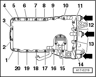
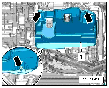
–  Fit sump and tighten bolts → Fig..
l  
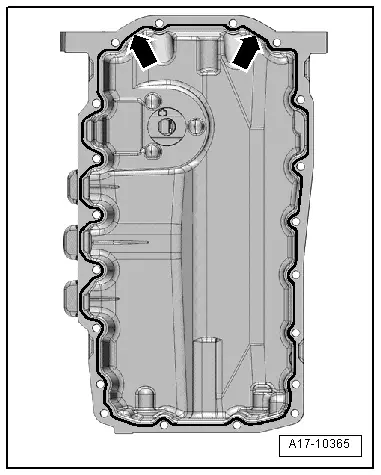
The sump must make flush contact with intermediate plate/gearbox flange.
  Note
t  When installing sump with engine removed from vehicle, ensure that sump is positioned flush with cylinder block at flywheel end.
t  After fitting sump assembly, the sealant must dry for approx. 30 minutes. Then (and only then) fill the engine with engine oil.
Remaining installation steps are carried out in reverse sequence; note the following:
  Note
Secure all hose connections with the correct type of hose clips (same as original equipment) → Electronic parts catalogue.
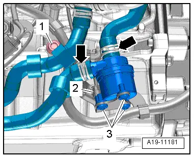
–  Install pump for exhaust gas recirculation cooler -V400- → Chapter.
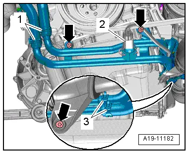
–  Install coolant pipes (right-side) → Chapter.
–  Install air pipes → Chapter.
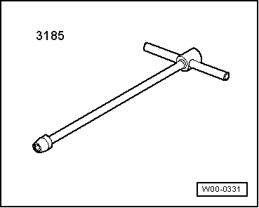
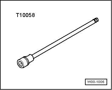
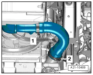
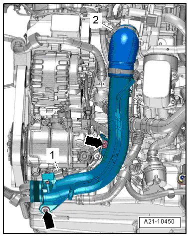
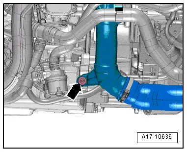
–  Install air hoses with screw-type clips → Fig..
–  Fill with engine oil and check oil level → Booklet819.
  A17-0219

Removing and installing oil pump > < Removing and installing oil level and oil temperature senderG266