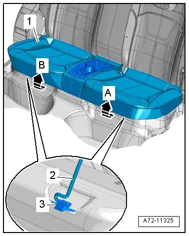
| Fuel gauge sender -G- installed: |
| –
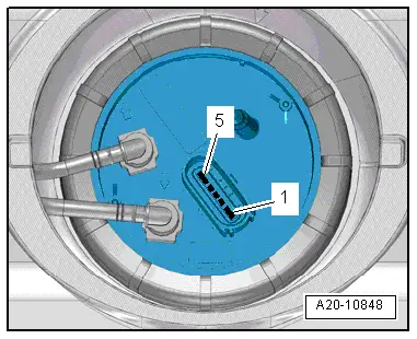
| Connect multimeter (resistance test) between contacts -2- and -3-. |
| l
| Sender at lower stop: 266 … 274 Ω. |
| l
| Sender at upper stop: 67 ... 73 Ω. |
| –
| Connect multimeter (resistance test) between contacts -2- and -4-. |
| l
| Sender at lower stop: 67 … 73 Ω. |
| l
| Sender at upper stop: 266 ... 274 Ω. |
| –
| Connect multimeter (resistance test) between contacts -3- and -4-. |
| l
| Sender in any position: 335 ... 345 Ω. |

Note | t
| If the resistance is 0 Ω, there is a short circuit. If the resistance is ∞ Ω, there is an open circuit in the wiring. |
| t
| To test the maximum and minimum resistance values for „tank full“ and „tank empty“, remove the fuel delivery unit and move the sender float all the way to its top or bottom position. |
| t
| The following values are obtained with the fuel delivery unit removed, due to the greater travel of the float arm: |
| Fuel gauge sender -G- removed: |
| –
| Connect multimeter (resistance test) between contacts -2- and -3-. |
| l
| Sender at lower stop: 285 … 295 Ω. |
| l
| Sender at upper stop: 48 ... 52 Ω. |
| –
| Connect multimeter (resistance test) between contacts -2- and -4-. |
| l
| Sender at lower stop: 48 … 52 Ω. |
| l
| Sender at upper stop: 285 ... 295 Ω. |
| –
| Connect multimeter (resistance test) between contacts -3- and -4-. |
| l
| Sender in any position: 335 ... 345 Ω. |
| –
| If test readings differ significantly from specifications, or if reading is 0 Ω (short circuit) or ∞ Ω (open circuit) and no fault is found in wiring, renew fuel gauge sender -G-. |
| –
| Removing and installing fuel gauge sender -G- → Chapter. |
|
|
|