audi Workshop Repair Guides

Audi Workshop Service and Repair Manuals

Removing and installing drive shaft (right-side) > < Slackening and tightening 12-point nut for outer joint on drive shaft
Removing and installing drive shaft (left-side)
Special tools and workshop equipment required
   
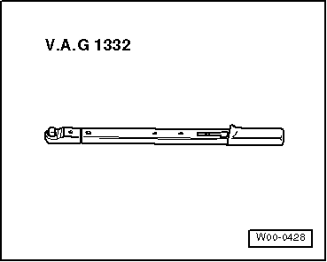
t  Torque wrench -V.A.G 1331-
  W00-0428
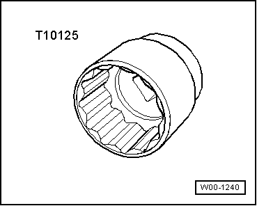
t  Socket AF 36 mm -T10125-
Removing
–  Lift vehicle far enough to take weight off front axle.
–  Unscrew 12-point nut from drive shaft using socket AF 36 mm -T10125- → Chapter.
–  Remove wheel.
–  Remove noise insulation → Rep. gr.66.
  W00-1240
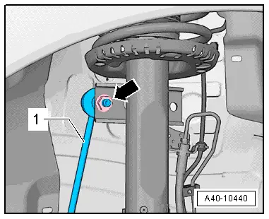
–  Unscrew nut -arrow- on both sides and pull coupling rod -1- out of suspension strut.
–  Turn anti-roll bar upwards with coupling rods -1- (left and right).
–  Unbolt drive shaft from flange shaft on gearbox.
  A40-10440
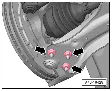
–  Unscrew nuts -arrows-.
–  Pull wishbone out of swivel joint.
  Note
When removing and installing, take care not to damage the rubber boot of the swivel joint. The boot should be protected against damage if necessary.
  A40-10429
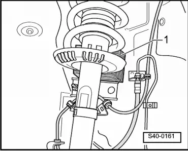
–  Pivot suspension strut outwards and support with a wooden block -1- or similar; at the same time pull drive shaft out of wheel bearing and remove outwards.
If the drive shaft cannot be pulled out of the wheel bearing by hand, use press tool -3283-.
Installing
Installation is performed in reverse sequence; note the following:
Remove any paint residue and/or corrosion on thread and splines of outer joint.
  S40-0161
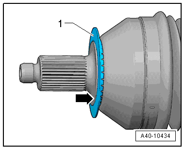
Important: Make sure that deflector ring -1- is clipped completely onto outer joint.
  Note
Deflector ring -1- must be flush with contact surface of outer joint -arrow-.
–  Guide outer joint into wheel hub splines as far as possible.
  A40-10434
–  Bolt swivel joint to wishbone with new nuts -arrows-.
Ensure sealing boot is not damaged or twisted.
–  Place inner joint of drive shaft in position and tighten bolts in diagonal sequence to 10 Nm.
–  Tighten multi-point socket-head bolts diagonally to the specified torque.
Tightening torque → Chapter „Exploded view - subframe, swivel joint, wishbone, anti-roll bar, coupling rod“
Tightening torque → Chapter „Exploded view - drive shaft with constant velocity joint VL90 or VL100“
Tightening torque → Chapter „Exploded view - drive shaft with constant velocity joint VL107“
Tightening torque → Chapter „Exploded view - drive shaft with triple roller joint AAR 2000/108“
–  Tighten 12-point nut on drive shaft using socket AF 36 mm -T10125- → Chapter.
–  Fit and secure wheel → Rep. gr.44.
  A40-10429

Removing and installing drive shaft (right-side) > < Slackening and tightening 12-point nut for outer joint on drive shaft