Note | t
| An absolute pressure of 0 bar represents an absolute vacuum. Normal ambient pressure thus corresponds to roughly 1 bar absolute. On the dials of most pressure gauges 0 bar is equivalent to an absolute pressure of one bar (recognisable by the datum -1 below 0). |
| t
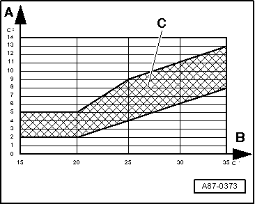
| The pressure in the refrigerant circuit depends on the ambient temperature. Due to heat irradiated by components (e.g. the radiator fan) a rather higher pressure is indicated for a warm engine than that displayed for the relevant ambient temperature. |
| t
| If the displayed pressure is lower than that given in the table: |
| t
| Check the measured value for the high-pressure sender for the air conditioner -G65- → Chapter (“Read the measured value block”) and → Chapter (“Electrical Check Step 5”) |
| t
| If no fault can be found on the high-pressure sender for the air conditioner -G65-, this indicates that there is too little refrigerant in the circuit. The vehicle must be taken to a specialist air conditioner workshop. |
| –
| Open the “centre” dash panel vents. |
| –
| Set the operating and display unit for air conditioner/Climatronic -E87- to “Auto” mode. |
| –
| Select the temperature preselection “Lo” on the operating and display unit for air conditioner/Climatronic -E87-. |
| –
| Set the air vent direction on the operating and display unit for air conditioner/Climatronic -E87- to “dash panel vents”. |
| –
| Select the display group “001” → Chapter in the “Read measured value block” function → Chapter |
| –
| Check the display in the display zones: |
| –
| Display zone “2” shows a signal ratio of greater than 30% (the air conditioner compressor regulating valve -N280- is actuated, the compressor is switched on). |
| –
| Display zone “1” shows a current greater than 0.3 A (the current is flowing via the air conditioner compressor regulating valve -N280-, the compressor is switched on). |
| –
| The pressure displayed in zone “4” rises above the value when the compressor is switched off. |
Note | t
| The air conditioner compressor regulating valve -N280- is actuated by the operating and display unit for air conditioner/Climatronic -E87- such that the temperature of the air downstream of the evaporator reaches the specified value (approx. 2 to 5 °C): Following the vehicle start, a value above 75 % (0.55 A) is displayed, dependent on the measured temperature, the engine speed, and the vehicle voltage. As soon as the temperature measured by the evaporator outlet temperature sender -G263- approaches the specified value, actuation is cancelled and the compressor output thus reduced. |
| t
| Under certain operating conditions, residual moisture in the coolant circuit may lead to the formation of ice on the air conditioner compressor regulating valve -N280-. Such ice formation impairs compressor control, the evaporator is cooled excessively and ices up. The icing-up of the evaporator may give rise to the following problems: |
| t
| Repeated or sporadic failure of the air conditioner (no cooling/heating output) after a long journey; the air conditioner functions properly again after a short delay following engine shutoff. |
| t
| Misting up of the windows on the inside after a long journey; the windows are initially not cleared even by pressing the “Defrost” button; the air conditioner functions properly again after a short delay following engine shutoff. |
| t
| Check the measured value of the evaporator outlet temperature sender -G263- → Chapter in the “Read measured value block” function, display group “007”. If the measured value of the sender is too low under the operating conditions described by the customer (at an ambient temperature over 0 °C , colder than 0 °C for a long period of time even though the air conditioner compressor regulating valve -N280- is currently not actuated), take the vehicle to a specialist air conditioner workshop. If the measured value is too large (e.g. greater than 10 °C even though the air conditioner is working properly, check the evaporator outlet temperature sender -G263-. |
| t
| Check the refrigerant pipe between the evaporator and the reservoir (thick pipe, low-pressure side) with the engine running. If this pipe is severely iced up when the problem occurs (a thin layer of ice is permissible), this also indicates that the evaporator temperature is too low and the vehicle is to be taken to a specialist air conditioner workshop. |
| t
| Make the specialist air conditioner workshop aware of the problem that you have encountered. The necessary work can only be performed by them (draining the refrigerant circuit, replacing the reservoir and subsequently evacuating the refrigerant circuit for at least 3 hours). |
| t
| If display zone “1” does not show sufficient current, or none at all, check the actuation of the air conditioner compressor regulating valve -N280- → Chapter (“Electrical Check Step 6”). |
| t
| If the pressure indicated in display zone “4” does not change and the compressor actuation is OK (display zones “1” and “2”), there is a fault in the refrigerant circuit and the vehicle is to be taken to a specialist air conditioner workshop. |
| –
| Press the button for the recirculated air flap (the symbol for “recirculated air mode” in the button lights up). |
| –
| Increase the engine speed to 2000 rpm (start of time measurement). |
| –
| Select the display group “007” → Chapter in the “Read measured value block” function → Chapter |
|
|
|