audi Workshop Repair Guides

Audi Workshop Service and Repair Manuals

Adjusting gear actuator > < Exploded view of gear actuator
Removing and installing gear actuator
Special tools and workshop equipment required
   
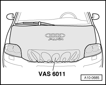
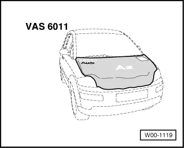
t  Protective cover for bonnet Audi A2 -VAS 6011-
  W00-1119
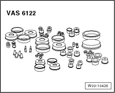
t  Engine bung set -VAS 6122-
Removing
  Caution
There is a risk of contamination from escaping hydraulic fluid.
The battery must be disconnected as the hydraulic pump starts up even with the ignition switched off.
When disconnecting the battery there is a risk of serious damage to electronic components:
Observe the correct procedure for disconnecting the battery.
–  Disconnect the earth wire at the battery → Rep. gr.27.
  W00-10435
–  Wash outside of bonnet and dry with a chamois leather.
–  Release service flap from inside.
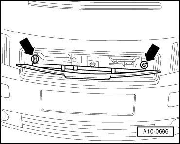
–  Release bonnet -arrows- and pull it forwards slightly.
  A10-0696
–  Fit the protective cover -VAS 6011- over the bonnet.
  Note
  A10-0685
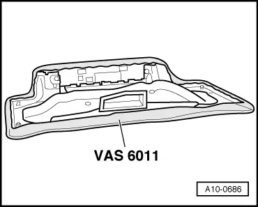
Do not store the bonnet in an upright position.
–  Detach the bonnet and set it down on the protective cover -VAS 6011-.
  A10-0686
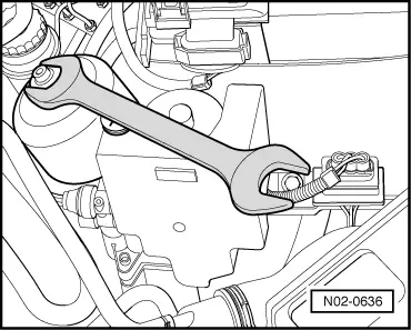
–  Unfasten the pressure accumulator by roughly 1/2 a turn.
l  The hydraulic fluid level in the reservoir increases.
  N02-0636
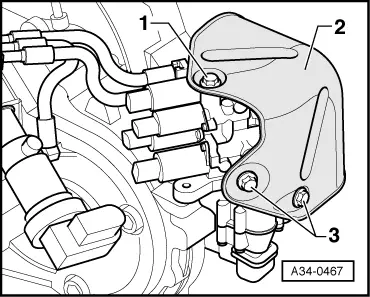
–  Remove the bolt -1- at the top of the gear actuator heat shield -2-.
  A34-0467
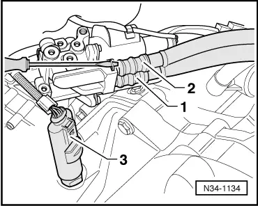
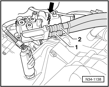
–  Use a screwdriver to prise the hose/pipe assembly clip out of the gear actuator.
–  Pull the hose/pipe assembly -1- and -2- out of the gear actuator.
–  Seal off open lines and connections with clean plugs from engine bung set -VAS 6122-.
–  Unplug the connector -3- at the vehicle speed sender -G68-.
  N34-1134
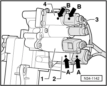
–  For re-installation, mark -arrows A, B- the connectors for the valves -2- and -4-.
–  Unplug electrical connectors at valves -1 … 4-.
  N34-1142
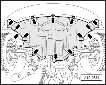
–  Remove the noise insulation -arrows-.
  A10-0684
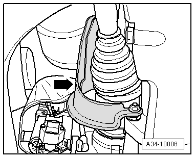
–  Unscrew the right drive shaft heat shield -arrow-.
  A34-10006
–  Remove the bolts -3- and detach the gear actuator heat shield -2-.
  A34-0467
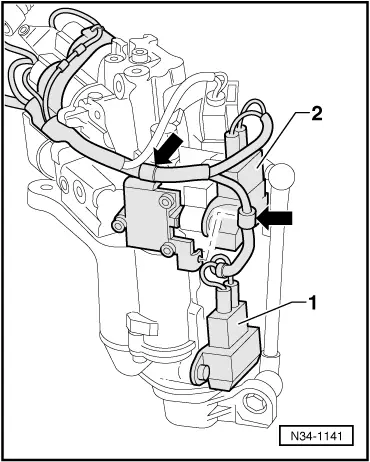
–  Unplug the connectors -1- and -2- at the gear detector potentiometers -G239-/-G240-.
–  Disengage -arrows- wiring harness from fasteners at gear actuator and move clear.
  N34-1141
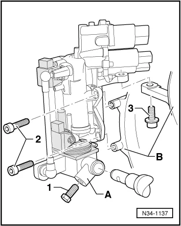
–  Slacken off the bolt -1- and detach the selector finger -A-.
–  Remove bolts -2- and -3-.
–  Detach the gear actuator from the gearbox -B- and carefully take out downwards.
  N34-1137
Installing
l  Tightening torque → Fig., → Fig..
Installation is carried out in reverse sequence; note the following:
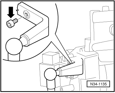
–  Remove the transportation safeguard bolt -arrow-.
  N34-1135
–  Use a tap to remove remnants of locking compound from the tapped hole in the selector finger -A-.
l  The gearbox must be in neutral.
–  Tighten the gear actuator bolts → Fig..
  N34-1137
–  Attach the wiring harness to the gear actuator -arrows-.
–  Plug in the connectors -1- and -2- at the gear detector potentiometers -G239-/-G240-, paying attention to the different wire lengths.
t  Long wire for gear detector potentiometer 1 -G239-.
t  Short wire for gear detector potentiometer 2 -G240-.
–  Use the current flow diagram to check wiring and connectors → Current flow diagrams, Electrical fault finding and Fitting locations.
–  Install noise insulation → Rep. gr.50.
  N34-1141
–  Fit the connectors in line with the marks -arrows A, B- made on removal.
1 - Connector for selector lever valve 1 -N284-
2 - Connector for selector lever valve 2 -N285-
3 - Connector for selector lever valve 3 -N286-
4 - Connector for selector lever valve 4 -N287-
–  Use the current flow diagram to check wiring and connectors → Current flow diagrams, Electrical fault finding and Fitting locations.
  N34-1142
  Caution
There is a risk of damage to the gear actuator.
t  Make sure the hose/pipe assemblies are fitted in accordance with the coloured marks → Fig..
t  If the hose/pipe assemblies have been incorrectly inserted, there is a risk of irreparable damage to the gear actuator on connecting the battery.
–  Plug in the connector at the vehicle speed sender -G68-.
–  Secure the pressure accumulator → Chapter.
–  Observe correct procedure after connecting battery → Rep. gr.27.
–  Switch on ignition (hydraulic fluid level in reservoir falls).
–  Perform a visual check for leaks in the hydraulic system.
–  Check the fluid level in the reservoir for the clutch mechanism and selector mechanism and replenish the fluid → Booklet809.
–  Adjust the gear actuator → Chapter.
  N34-1138

Adjusting gear actuator > < Exploded view of gear actuator