
A2
| Dismantling and assembling gearbox housing, selector mechanism, input shaft, output shaft (pinion shaft), differential and selector forks |

| Special tools and workshop equipment required |
| t | Thrust plate -40 - 105- |
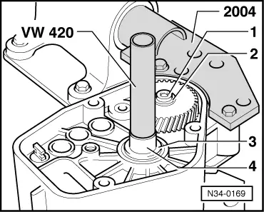
| t | Tube -VW 420- |
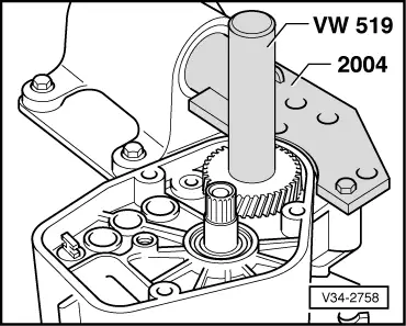
| t | Tube -VW 519- |
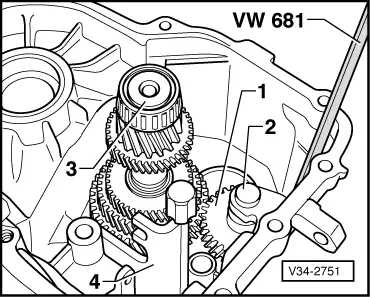
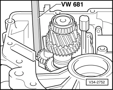
| t | Oil seal extractor lever -VW 681- |
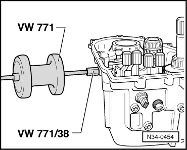
| t | Multi-purpose tool -VW 771- with -VW 771/38- and -VW 771/40- |
| t | Used oil collection and extraction unit -V.A.G 1782- |

| t | Extension -30 - 23- |
| t | Hot air blower -V.A.G 1416- |
| t | Torque wrench -V.A.G 1331- |
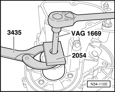
| t | Hexagon key -V.A.G 1669- |
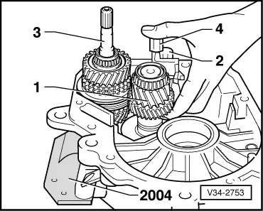
| t | Pressing-out tool -2054- |
| t | Counterhold tool -3435- |
|
|
|
|
|
|
|
|
|
|
|
|
|
|
|
|
|
|
|
|
|
|
|
|
|
|
|
|
|
|
|
|
|
|
|
|
|
|
|
|
|
|
|
|
|
|
|
|
 Note
Note
|
|
|
|
|
|
|
|
|
|
|
|
|
|
|
|
|
|
|
|
|
|
 WARNING
|
|
Note
|
|
| Available circlips - Thickness of circlips in mm | ||
| 2.0 | 2.3 | 2.6 |
| 2.1 | 2.4 | |
| 2.2 | 2.5 | |
|
|
|
|
|
|
|
|
|
|
|
|
|