
A2
| Exploded view of hose/pipe assemblies |

| 1 - | Pipe/hose assembly |
| q | Colour of connection pieces: „blue“ |
| q | Make a coloured mark on the hose/pipe assembly if necessary |
| q | Removing and installing → Chapter |
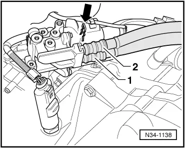
| q | Inserting in gear actuator → Fig. |
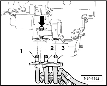
| q | Inserting with mounting plate in hydraulic control unit → Fig. |
| 2 - | Pipe/hose assembly |
| q | Colour of connection piece in mounting plate: „gold“ |
| q | Removing and installing with clutch slave cylinder |
| q | Removing and installing → Chapter |
| q | Inserting with mounting plate in hydraulic control unit → Fig. |
| 3 - | Pipe/hose assembly |
| q | Colour of connection pieces: „silver“ |
| q | Removing and installing → Chapter |
| q | Inserting in gear actuator → Fig. |
| q | Inserting with mounting plate in hydraulic control unit → Fig. |
| 4 - | O-ring |
| q | Renew |
| q | Take care not to interchange; for assignment refer to → Electronic parts catalogue |
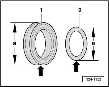
| q | Distinguishing feature → Fig. |
| 5 - | Spring pin |
| q | Renew |
| q | Drive in and drive out with drift |
| 6 - | Clutch slave cylinder |
| q | Removing and installing → Chapter |
| 7 - | O-ring |
| q | Renew |
| q | Different versions → Fig.; for correct version refer to → Electronic parts catalogue |
| 8 - | Assembly plate |
| q | Attachment with pipe/hose assemblies to hydraulic control unit → Fig. |
| 9 - | Bracket |
| q | holds hose/pipe assemblies in position |
| 10 - | Gear actuator |
| q | Removing and installing → Chapter |
| 11 - | Clip |
| q | Renew |
|
|
|
|
| Item | Fitting location | Dimension -a- (mm) | Contour -Arrow- |
| -1- | Clutch slave cylinder | 10 | angular |
| -2- | Hydraulic control unit, gear actuator | 8 | round |