
A2
|
|
|
|
|
 Note
Note
|
|
|
|
|
|
Note
|
|
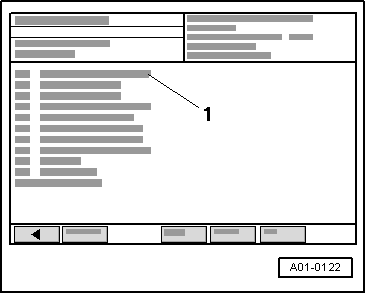
| Indicated on display: |
| Display zones | Explanations | |
| 1 | WAIT! | Do nothing while this is displayed. Wait until the -VAS 5051 A- switches to the next display |
| 2 | Ignore display zones | |
| 3 | ||
| 4 | ||
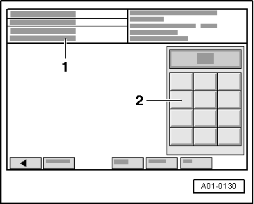
| Next readout on display: |
| Display zones | Explanations | |||
| 1 | ADJUST! → Note |
| ||
| 2 | Ignore display zones | |||
| 3 | ||||
| 4 | ||||
Note
|
|
Note
Note
|
|
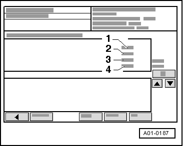
| Next readout on display: |
| Display zones | Explanations | |
| 1 | WAIT! | Do nothing while this is displayed. Do not press brake pedal. Do not touch selector lever. The control unit shifts through a few gears and outputs various codes in the process. Please wait! |
| 2 | 0 | Gearbox position: Possible values are: 0 … 28; for display value 28 the -VAS 5051 A- switches to the next display. Ignore this display zone |
| 3 | 0 | Ignore display zones |
| 4 | 1.99 V | |
| Next readout on display: |
| Display zones | Explanations | |||
| 1 | (–)! |
| ||
| 2 | 28 | Ignore display zones | ||
| 3 | 0 | |||
| 4 | 4.00 V | |||
| Next readout on display: |
| Display zones | Explanations | |||||||
| 1 | STOP! |
| ||||||
| 2 | 28 | Ignore display zones | ||||||
| 3 | 0 | |||||||
| 4 | 4.00 V | |||||||
| Next readout on display: |
| Display zones | Explanations | |||
| 1 | KickDown! |
| ||
| 2 | 28 | Ignore display zones | ||
| 3 | 0 | |||
| 4 | 4.00 V | |||
| Next readout on display: |
| Display zones | Explanations | |||||||||
| 1 | N! |
| ||||||||
| 2 | 28 | Ignore display zones | ||||||||
| 3 | 0 | |||||||||
| 4 | 4.00 V | |||||||||
| Next readout on display: |
| Display zones | Explanations | |||
| 1 | StartMot! → Note |
| ||
| 2 | 28 | Ignore display zones | ||
| 3 | 0 | |||
| 4 | 4.00 V | |||
| 2) | After the prompt “StartMot!” the connection between control unit and -VAS 5051- may be interrupted/break off. Continued procedure → Chapter. |
| Next readout on display: |
| Display zones | Explanations | |
| 1 | SEARCHNG! | Do nothing while this is displayed. Do not press brake pedal. Do not touch selector lever. Allow engine to continue running. The control unit is independently searching for the clutch's slip point |
| 2 | 28 | Ignore display zones |
| 3 | 0 | |
| 4 | 4.00 V | |
| Next readout on display: |
| Display zones | Explanations | |||||||||
| 1 | IGN.OFF! |
| ||||||||
| 2 | 28 | Ignore display zones. | ||||||||
| 3 | 0 | |||||||||
| 4 | 4.00 V | |||||||||
|