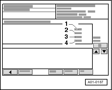
audi Workshop Repair Guides

Audi Workshop Service and Repair Manuals

Vehicle electrics > < Basic setting cannot be performed
Vehicle does not start
Special tools and workshop equipment required
   
t  Protective cover -VAS 6011-
Test sequence
–  Interrogate fault memory → Chapter, eliminate any faults displayed and erase fault memory → Chapter.
–  Try again to start the vehicle.
If there are no faults in the fault memory, but the vehicle does not start:
–  Wash and polish outside of bonnet with a chamois leather.
–  Release the service flap from inside.
  W00-1119
–  Release bonnet -arrows- and pull it forwards slightly.
  A10-0696
–  Clamp the protective cover -VAS 6011- over the bonnet.
  A10-0685
–  Remove the bonnet and lay it down on the side of the protective cover of the -VAS 6011-.
  Note
Do not set the bonnet down on the points.
–  Apply handbrake.
–  Switch on ignition.
  A10-0686
–  Shift selector lever to position “STOP” and release the brake pedal.
l  With ignition on, selector lever in “STOP” and brake pedal not pressed, the clutch must be engaged.
–  Read measured value block 002 → Chapter.
Display on -VAS 5051 A-:
–  Check display in zone -2-.
l  Specified value: Less than 3.5 V.
If the specified value is exceeded, the clutch is disengaged and the electronic manual gearbox control unit -J514- is in emergency running mode.
–  Perform test → Chapter „Voltage value of the clutch travel sender -G162- cannot be adjusted“.
If reading matches specification:
  A01-0187
–  By pressing the key twice, switch to measured value block 004 → Anchor.
–  Check the last digit (on the far right) of the display in display zone -2-.
–  Press the brake pedal.
l  Specified value: Display “XXXXXXX1” = brake pedal operated.
–  Release the brake pedal.
l  Specified value: Display “XXXXXXX0” = brake pedal not operated.
  Note
Ignore the digits represented by “X”.
If readout is not as described:
–  Interrogate fault memory of engine control unit.
–  If necessary, check brake light switch -F-/brake pedal switch -F47- → Current flow diagrams, Electrical fault finding and Fitting locations.
–  Check the brake pressure switch -F270- in the electrical test, test step 9 → Anchor.
If the vehicle still does not start:
–  Check the system for leaks → Chapter.
If the vehicle still does not start:
  A01-0187
–  Read measured value block 004, display zone -3- → Anchor.
–  Check the second to last digit (on the right) of the display in display zone -3-.
–  Turn ignition key to “Start engine” position.
l  Specified value: Display “XXXXXX0X” = starter inhibitor and reversing light relay -J226- is actuated.
–  Release ignition key from “Start engine” position.
l  Specified value: Display “XXXXXX1X” = starter inhibitor and reversing light relay -J226- is not actuated.
  Note
Ignore the digits represented by “X”.
If readout is not as described:
–  Check the starter inhibitor and reversing light relay -J226- → Current flow diagrams, Electrical fault finding and Fitting locations.
–  Check the electrical connectors and the wiring → Current flow diagrams, Electrical fault finding and Fitting locations.
–  Check the starter power supply of terminal 50.
If the vehicle still does not start:
–  Perform the final control diagnosis of the “hydraulic control unit” → Chapter.
–  Perform the “gear actuator” final control diagnosis → Chapter.
  A01-0187

Vehicle electrics > < Basic setting cannot be performed