audi Workshop Repair Guides

Audi Workshop Service and Repair Manuals

Removing and installing charge air cooler > < Turbocharger - exploded view of components
Removing and installing turbocharger
Special tools and workshop equipment required
   
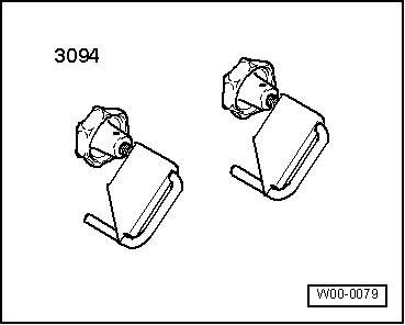
t  Hose clamps for hoses up to 25 mm Ø -3094-
  W00-0079
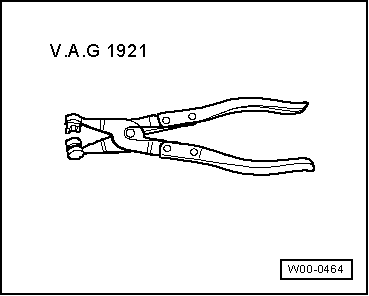
t  Hose clip pliers -V.A.G 1921-
Removing
–  Remove bonnet → Chapter.
  W00-0464
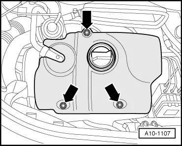
–  Take off engine cover panel -arrows-.
–  Remove noise insulation located below (detach crankcase breather hose).
  A10-1107
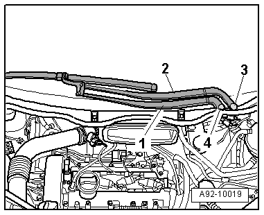
–  Use screwdriver to lever of cover caps -3- and -4- from wiper arms.
–  Slacken nuts on both wiper arms a few turns.
–  Loosen wiper arms -1- and -2- from wiper shafts by tilting slightly.
–  Completely remove nuts and take off wiper arms.
  A92-10019
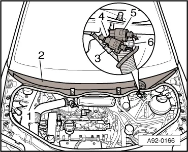
–  Disconnect washer fluid hose -3-.
–  If fitted, unplug electrical connectors -4- and -5- for heated washer jets.
–  Open hose clip -6- using hose clip pliers -V.A.G 1921- and detach water drain hose from cowl panel grille.
–  Pull off rubber seal -1- on cowl panel grille.
–  Disconnect cowl panel grille -2-.
  A92-0166
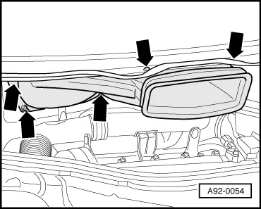
–  Unscrew nuts and bolts -arrows-.
–  Pull air duct forwards, move it to right side of vehicle and remove.
  A92-0054
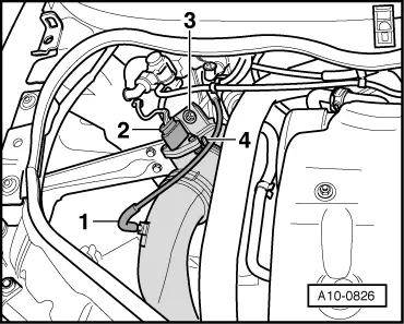
–  Unplug electrical connector -2- at air mass meter -G70-.
–  Detach vacuum hose -1-.
–  Release hose clip -4- and remove air pipe with air mass meter -G70-.
–  Unscrew nut -3-.
  A10-0826
–  Remove air intake hose -2- between charge air cooler and intake manifold.
  Note
Disregard -item 1-.
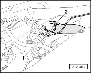
  A10-0830
–  Disconnect vacuum hose -1- from mechanical exhaust gas recirculation valve.
–  Disconnect vacuum hose -2- from throttle butterfly valve -N211-.
  WARNING
t  In extreme cases the fuel lines and the fuel can reach a temperature of 100 °C on vehicles with unit injector engine. Allow the fuel to cool down before disconnecting the lines - danger of scalding.
t  Wear protective gloves.
t  Wear safety goggles.
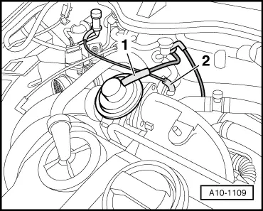
  A10-1109
–  Mark fuel supply pipe -2- and fuel return pipe -1-.
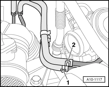
  A10-1117
–  Unscrew bolts -arrows- and detach air pipe from turbocharger.
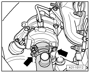
  A21-10112
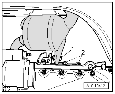
–  Remove bolts -2- on bracket for starter catalytic converter.
  Note
Disregard -item 1-.
  A10-10412
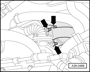
–  Unscrew nuts -arrows- at turbocharger/starter catalytic converter.
  Note
Do not bend the flexible joint (de-coupling element) between starter catalytic converter and main catalytic converter more than 10°, otherwise it could be damaged.
–  Disconnect starter catalytic converter from turbocharger.
–  Tie up starter catalytic converter to body.
  A26-0468
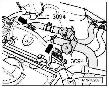
–  Clamp off coolant hoses going to exhaust gas recirculation cooler with hose clamps -3094-.
–  Detach coolant hoses -arrow- at exhaust gas recirculation cooler.
  A19-10260
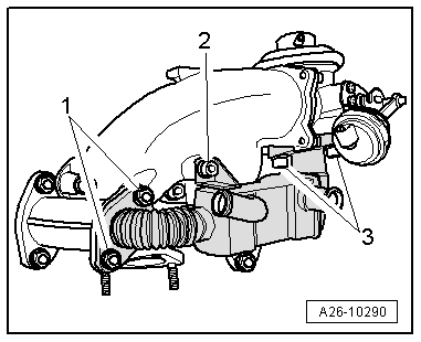
–  Remove bolts -2- and -3- and also nuts -1- and take off exhaust gas recirculation cooler.
  A26-10290
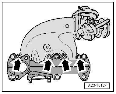
–  Unscrew bolts -arrows- and remove intake manifold.
  A23-10124
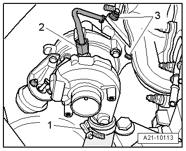
–  Detach air intake hose -1- from turbocharger.
–  Unscrew oil supply pipe -2- from turbocharger.
–  Unscrew the 3 turbocharger nuts -3-.
  A21-10113
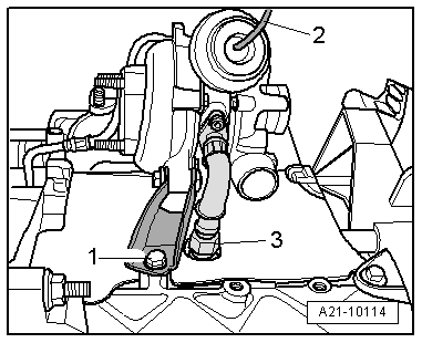
–  Detach vacuum hose -2- leading to vacuum unit for charge pressure control and move it clear.
–  Remove oil return pipe -3- at cylinder block.
–  Unbolt support -1- for turbocharger from cylinder block.
–  Lift out turbocharger.
Installing
Installation is carried out in the reverse order; note the following:
  Note
t  Renew gaskets, seals and self-locking nuts.
t  Fill turbocharger with engine oil at connection for oil supply pipe.
t  Charge air system must be free of leaks.
t  Hose connections and hoses for charge air system must be free of oil and grease before assembly.
t  Secure all hose connections with the correct type of hose clips (same as original equipment) → Parts catalogue.
–  Install intake manifold.
–  Install starter catalytic converter together with main catalytic converter → Chapter.
–  Install and adjust wiper arms → Rep. Gr.92.
–  Check oil level → Chapter.
  Note
After installing turbocharger, allow engine to idle for approx. 1 minute and do not rev up immediately to ensure turbocharger is supplied with oil.
Tightening torques
  A21-10114
ComponentNm
Turbocharger to exhaust manifold25 1)
Support for turbocharger to cylinder block20
Oil return pipe to cylinder block30
Oil supply pipe to turbocharger22
Intake manifold to cylinder head25
Exhaust gas recirculation cooler toMechanical exhaust gas recirculation valve25
Intake manifold25
Exhaust manifold25 1)
Air pipe to turbocharger8
l  1) Renew nuts.


Removing and installing charge air cooler > < Turbocharger - exploded view of components