
A2
 Note
Note
|
Note
|
|
|
|
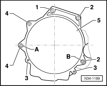
| Item | Bolt | Nm | ||||||
| 1 1), 2 | M12x55 | 80 | ||||||
| 3 | M10x50 | 40 | ||||||
| 4 1)2) | M12x150 | 80 | ||||||
| 5 3) | M6x12 | 10 | ||||||
| A, B | Dowel sleeves for centralising | |||||||
| ||||||||
|
Note
|
|
Note
|
|
 Caution
| Component | Nm | ||
| Bolts/nuts | M6 | 9 | |
| M7 | 15 | ||
| M8 | 20 | ||
| M10 | 40 | ||
| M12 | 65 | ||
| Except for the following: | |||
| Battery plus (+) cable to starter | 16 | ||
| Earth wire to gearbox | 22 | ||
| Bracket for wiring harness to coolant hose/pipe connection | 10 | ||
| Drive shaft heat shield to cylinder block | 33 | ||
| Air pipe to: | Turbocharger | 8 | |
| Sump | 8 | ||
| Body | 8 | ||
| Engine cover panel to bracket | 5.5 | ||