audi Workshop Repair Guides

Audi Workshop Service and Repair Manuals

Engine lubrication > < Checking valves
Machining valve seats
  Note
t  If a good seating pattern cannot be obtained by grinding the valve seats (lapping), they must be refaced (machined).
t  When servicing engines with leaking valves, it is not sufficient to machine (reface) the valve seats and renew the valves. The valve guides must also be checked for wear. This is particularly important on high-mileage engines → Chapter.
t  
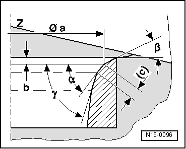
Valve seats should only be machined to the extent required to give a proper seating pattern.
t  
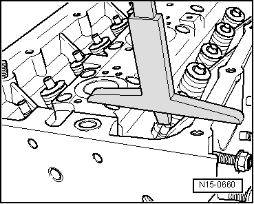
The maximum permissible machining dimension must be calculated before starting work.
t  If the machining dimension is exceeded, the function of the hydraulic valve play compensation can no longer be guaranteed and the cylinder head must be renewed.
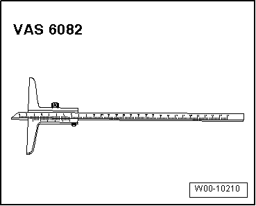
Special tools and workshop equipment required
   
t  Depth gauge -VAS 6082-
t  Valve seat machining tool
  W00-10210
A - Calculating maximum permissible machining dimension
–  Insert valve and press firmly against valve seat.
  Note
If the valve has to be renewed as part of a repair, use a new valve for the measurement.
–  Use depth gauge -VAS 6082- to measure distance between end of valve stem (upper edge) and top surface of cylinder head.
–  Calculate maximum permissible machining dimension from measured distance and minimum dimension.
l  Minimum dimension for inlet valve and exhaust valve: 7.6 mm.
   Measured distance minus minimum dimension = max. permissible machining dimension.
  N15-0660
Example:
Measured distance8.0 mm
Minimum dimension– 7.6 mm
Maximum permissible machining dimension= 0.4 mm

  Note
t  If the calculated maximum permissible machining dimension is 0 mm or less than 0 mm, repeat the measurement with a new valve.
t  If the result is again 0 mm or less than 0 mm, renew the cylinder head.
   
B - Machining valve seats
Inlet valve seat
a - Ø 28.7 mm
b - Maximum permissible machining dimension
c - 1.5 … 1.8 mm
Z - Bottom surface of cylinder head
α - 45° valve seat angle
β - 30° upper correction angle
γ - 60° lower correction angle
Exhaust valve seat
a - Ø 25.0 mm
b - Maximum permissible machining dimension
c - approx. 1.8 mm
Z - Lower edge of cylinder head
α - 45° valve seat angle
β - 30° upper correction angle
γ - 60° lower correction angle
  Note
Calculating maximum permissible machining dimension → Anchor.
  N15-0096

Engine lubrication > < Checking valves