audi Workshop Repair Guides

Audi Workshop Service and Repair Manuals

Crankshaft > < Removing and installing flywheel
Removing and installing sealing flange (gearbox end)
Special tools and workshop equipment required
   
t  Open ring spanner insert -V.A.G 1332/9-
  W00-0631
t  Camshaft lock -T10016-
  W00-0594
t  Assembly tool -T10017-
t  Electric drill with plastic brush attachment
t  Safety goggles
t  Sealant → Parts catalogue
Procedure
l  Gearbox removed.
  Note
For illustration purposes, the procedure is shown with the engine removed.
  W00-0630
Pressing sealing flange with sender wheel off crankshaft
–  Remove flywheel → Chapter.
–  Press intermediate plate off dowel sleeves -arrows B- and detach from top of sealing flange -arrow A-
  A13-10521
–  Release retaining clips -arrows- and detach cover (top) for toothed belt.
  A13-10528
–  Rotate crankshaft in normal direction of rotation to „TDC“.
l  Notch on crankshaft pulley must align with edge of marking -O-.
  N13-0451
l  The locating holes in the camshaft sprockets must align with the corresponding holes in the camshaft housing -arrows-.
  Note
If the locating holes are positioned on the opposite side, the crankshaft must be turned one revolution further.
  N13-0155
–  Lock camshafts using camshaft lock -T10016-:
l  It should be possible to insert one locking pin through the locating hole in the inlet camshaft sprocket -C- and into the corresponding hole in the camshaft housing.
l  It should be possible to insert the second locking pin through the locating hole in the exhaust camshaft sprocket and into the corresponding hole in the camshaft housing.
l  The knobs on locking pins must be on a level -line A-.
–  Remove sump → Chapter.
  N13-0369
–  Remove bolt -arrow- and detach engine speed sender -G28-.
  N13-10083
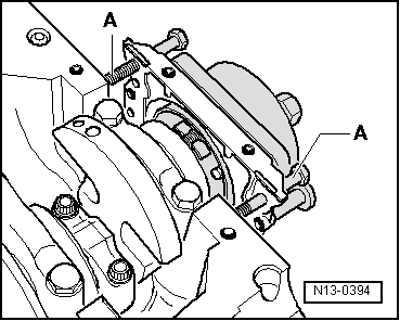
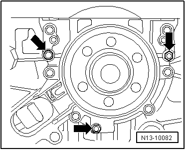
–  Remove bolts for sealing flange.
  Note
The sealing flange is pressed off the crankshaft together with the sender wheel.
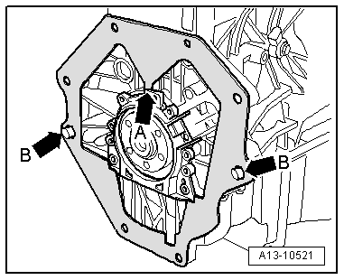
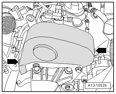
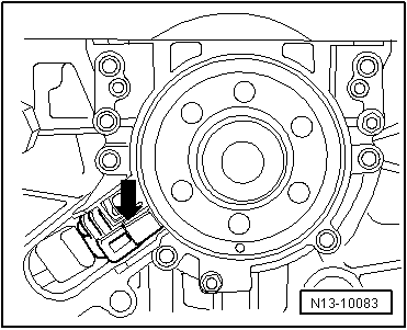
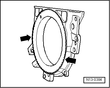
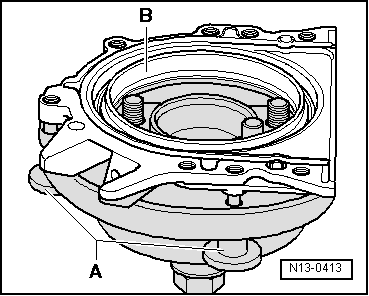
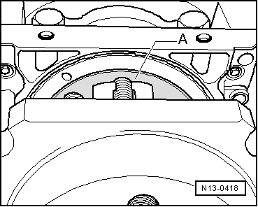
–  To press off, screw 3 bolts M6x35 -arrows- alternately into sealing flange not more than 1/2 turn at a time.
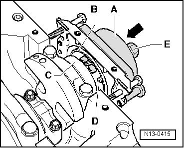
–  Take off sealing flange with sender wheel.
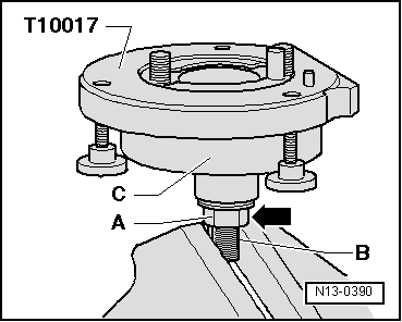
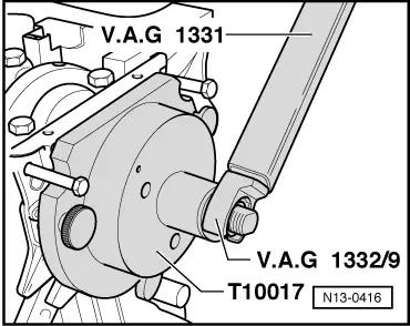
Pressing in sealing flange with sender wheel
  Note
t  
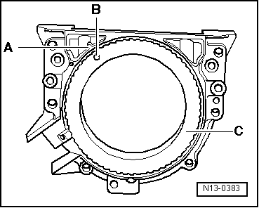
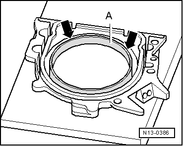
The sealing flange with PTFE oil seal is fitted with a sealing lip support ring. This support ring acts as an assembly sleeve and must not be removed before installation.
t  
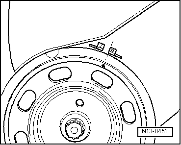
Sealing flange and sender wheel must not be separated or rotated out of position after removal from packaging.
t  
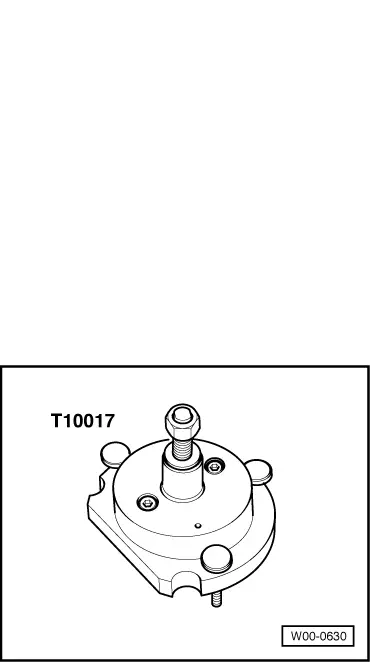
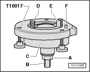
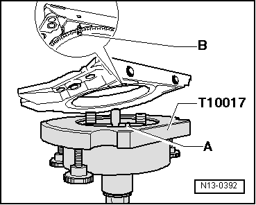
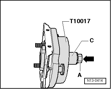
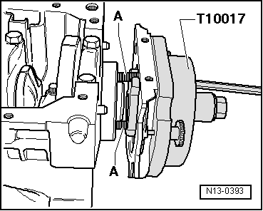
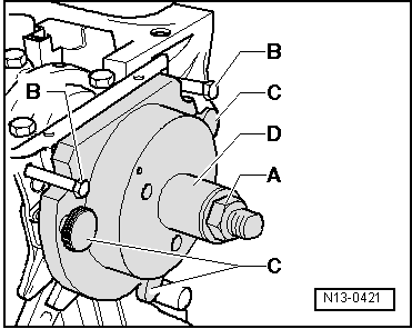
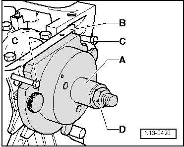
The sender wheel is held in its installation position by a locating pin on the assembly tool -T10017-.
t  The sealing flange and oil seal are one unit and can only be replaced together with the sender wheel.
t  
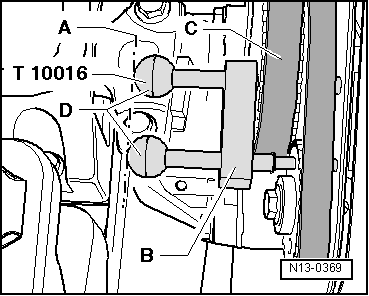
The assembly tool -T10017- is held in the correct position relative to the crankshaft by a guide pin which is inserted into a hole in the crankshaft.
  N13-10082
Construction of assembly tool -T10017-:
A - Nut
B - Tightening flats
C - Assembly housing
D - Hexagon socket-head bolt
E - Guide pin
F - Locating pin
  N13-0388
A - Fitting sealing flange with sender wheel onto assembly tool -T10017-:
–  Unscrew nut -A- until it is just in front of flats -B- on threaded spindle.
–  Clamp assembly tool -T10017- in a vice on flats of threaded spindle.
–  Press the assembly housing -C- downwards so that it lies on the nut -arrow-.
l  Inner part of assembly device and assembly housing must align (be level) with each other.
  N13-0390
–  Remove the securing clip -A- from new sealing flange.
  Note
The sender wheel must not be taken out of the sealing flange or rotated out of position.
  N13-0391
l  The locating hole -B- on the sender wheel -C- must align with the marking -A- on the sealing flange.
  N13-0383
–  Place the sealing flange (with the front side downwards) on a clean flat surface.
–  Press the sealing lip support ring -A- downwards in direction of -arrows- until it lies against the flat surface.
  N13-0386
l  The upper edge of the sealing lip support ring must be flush with the front edge of the sealing flange -arrows-.
  N13-0384
–  Place front side of sealing flange on assembly tool -T10017-, so that locating pin -A- can be inserted in hole -B- in sender wheel.
l  Ensure the sealing flange lies flat on the assembly tool.
  N13-0392
–  Press the sealing flange and sealing lip support ring -B- onto the surface of the assembly tool -T10017- while tightening the 3 knurled screws -A- so that the locating pin will not slip out of the hole in the sender wheel.
  Note
Ensure that the sender wheel remains fixed on the assembly tool when installing the sealing flange.
  N13-0413
B - Installing assembly tool -T10017- with sealing flange on crankshaft flange:
l  Crankshaft flange must be free of oil or grease.
l  Engine is at „TDC“ position.
–  Screw nut -A- to end of threaded spindle.
–  Press the threaded spindle of assembly tool -T10017- in direction of -arrow- until the nut -A- lies on the assembly housing -C-.
  N13-0414
–  Position flat edge of assembly housing towards sealing surface for sump on cylinder block.
–  Secure assembly tool -T10017- to crankshaft flange by screwing hexagon socket head bolts -A- approx. 5 threads into crankshaft flange.
  N13-0393
–  Screw two bolts M6×35 mm -item A- into cylinder block to guide sealing flange.
  N13-0394
C - Securing assembly tool -T10017- onto crankshaft flange:
–  Press the assembly housing -A- by hand in the direction of the crankshaft flange -C--arrow- until the sealing lip support ring -B- lies on the surface of the crankshaft flange.
–  Push guide pin -D- into hole in crankshaft. This brings the sender wheel into its final installation position.
–  Tighten the two hexagon socket head bolts on assembly tool hand-tight.
–  Screw nut -E- onto threaded spindle by hand until it lies against the assembly housing -A-.
  N13-0415
D - Pressing sender wheel onto crankshaft flange with assembly tool -T10017-:
–  Tighten nut on assembly tool -T10017- to 35 Nm.
l  A small air gap must be present between cylinder block and sealing flange after tightening nut to 35 Nm.
  N13-0416
E - Checking installation position of sender wheel on crankshaft:
–  Screw nut -A- to end of threaded spindle.
–  Remove both bolts M6x35 -item B- from cylinder block.
–  Unscrew the three knurled screws -C- from sealing flange.
–  Detach assembly tool -T10017- and sealing lip support ring.
  N13-0421
–  Apply depth gauge to crankshaft flange -A-.
  N13-0418
–  Use feeler gauge -A- to measure between depth gauge and sender wheel.
  N13-0419
–  Measure distance -a- between crankshaft flange -A- and sender wheel -B-.
l  Specification: Distance -a- = 0.5 mm.
–  Press sender wheel in further if distance is too small → Anchor.
–  If reading matches specification, continue with assembly → Anchor.
  N13-0417
F - Pressing sender wheel in further:
–  Slide assembly housing -A- onto sealing flange -B- by hand.
–  Screw two bolts M6×36 mm -item C- into cylinder block to guide sealing flange -B-.
–  Screw nut -D- onto threaded spindle by hand until it lies against the assembly housing.
  N13-0420
–  Tighten nut on assembly tool -T10017- to 40 Nm.
–  Check installation position of sender wheel on crankshaft again → Anchor.
–  Tighten nut on assembly tool -T10017- to 45 Nm if distance is too small.
–  Check installation position of sender wheel on crankshaft again → Anchor.
  N13-0416
Assembling
l  Tightening torque → Chapter
  Note
Renew sealing flange bolts.
–  Install engine speed sender -G28- → Fig..
–  Install sump → Anchor.
–  Engage intermediate plate at top of sealing flange -arrow A- and push onto dowel sleeves -arrows B-.
–  Install flywheel → Chapter.
  A13-10521

Crankshaft > < Removing and installing flywheel