audi Workshop Repair Guides

Audi Workshop Service and Repair Manuals

Checking engine speed sender > < Checking intake air temperature sender
MM-MPI injection and ignition system (4-cylinder)
Checking components
Checking coolant temperature sender

Special tools, workshop equipment, testers, measuring instruments and auxiliary items required

  • ◆ Fault reader V.A.G 1551 or vehicle system tester V.A.G 1552 with cable V.A.G 1551/3A
  • ◆ Test box V.A.G 1598/31
  • ◆ Hand multimeter V.A.G 1526 or multimeter V.A.G 1715
  • ◆ Adapter set V.A.G 1594
  • ◆ Current flow diagram

Test sequence

  • ‒ Connect the fault reader V.A.G 1551 (V.A.G 1552). Then switch ignition on and select engine control unit with the "Address word" 01.
    (Connecting fault reader and selecting engine control unit .)
 
→ Indicated on display:
Rapid data transfer    HELP
Select function XX
  • ‒ Press keys 0 and 8 for the function "Read measured value block" and confirm entry with Q key.
 
→ Indicated on display:
Read measured value block    HELP
Input display group number XXX
  • ‒ Press keys 0, 0 and 1 for "Display group number 1" and confirm entry with Q key.
 
→ Indicated on display:
(1...4 = Display zones)
Read measured value block    1    ⇒
    1    2    3    4
  • ‒ Note coolant temperature value in display zone 2.

Display

Cause

Continuation of check

-40 °C

Open circuit or short to positive

=> Page 24-68

120 °C

Short to earth

=> Page 24-70

Approx. coolant temperature1)

---

Only if sporadic faults have
been
detected:2)
=> Page 24-72

    1)    If a temperature is displayed which deviates greatly from the ambient temperature of the sender, check sender wiring for transfer resistances.

    2)    Check is only possible when the engine is cold.

Continuation of check when display shows -40 °C:

  • ‒ Unplug 4-pin connector from coolant temperature sender (G62) with coolant temperature gauge sender (G2).
  • ‒ Fitting locations
 
N24-1040
  • ‒ → Bridge connector contacts 3+4 using adapter cables from V.A.G 1594 and observe display.

If the display jumps to 120 °C:

  • ‒ Press ⇒key.
  • ‒ Press keys 0 and 6 for the function "End output" and confirm entry with the Q key.
  • ‒ Switch off ignition.
  • ‒ Replace coolant temperature sender (G62) with coolant temperature gauge sender (G2) , item 16.

If the display remains at -40 °C:

  • ‒ Press ⇒key.
 
A24-0377
  • ‒ Press keys 0 and 6 for the function "End output" and confirm entry with the Q key.
  • ‒ Switch off ignition.
  • ‒ → Connect test box V.A.G 1598/31 to control unit wiring harness. The engine control unit remains disconnected => Page 24-8.

 
N24-1040
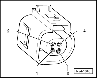
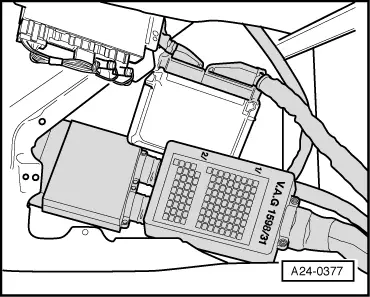
  • ‒ → Check wiring for open circuit between test box and 4-pin connector using current flow diagram.
        Contact 3 + socket 108
        Contact 4 + socket 93
        Wire resistance: Max. 1.5 ω
  • ‒ Check wiring additionally for short circuit to battery positive.
        Specification: ∞ω

If no fault is detected in the wiring:

  • ‒ Replace coolant temperature sender (G62) with coolant temperature gauge sender (G2) , item 16.

Continuation of check when display shows 120 °C:

  • ‒ Unplug 4-pin connector from coolant temperature sender (G62) with coolant temperature gauge sender (G2).
  • ‒ Fitting locations overview

If the display jumps to -40 °C:

  • ‒ Press ⇒key.
  • ‒ Press keys 0 and 6 for the function "End output" and confirm entry with the Q key.
  • ‒ Switch off ignition.
  • ‒ Replace coolant temperature sender (G62) with coolant temperature gauge sender (G2) , item 16.

If the display remains at 120 °C:

  • ‒ Press ⇒key.
  • ‒ Press keys 0 and 6 for the function "End output" and confirm entry with the Q key.
 
A24-0377
  • ‒ Switch off ignition.
  • ‒ → Connect test box V.A.G 1598/31 to control unit wiring harness. The engine control unit remains disconnected => Page 24-8.

 
N24-1040
  • ‒ → Check the wiring for open circuit between test box and 4-pin connector using current flow diagram.
        Contact 3+socket 93
        Contact 4+socket 108
        Wire resistance: Max. 1.5 ω
  • ‒ Check wiring additionally for short circuit to battery positive.
        Specification: ∞ω

If no fault is detected in the wiring:

  • ‒ Replace coolant temperature sender (G62) with coolant temperature gauge sender (G2) , item 16.

Continuation of check when display = coolant temperature:

Test conditions

  • ● Engine must be cold.

Functional check of sender

  • ‒ Connect fault reader V.A.G 1551 (V.A.G 1552). Start engine and select "Address word" 01 of engine control unit. When doing this the engine must be running at idling speed.
    (Connecting fault reader and selecting engine control unit
    => Page 01-13.)
 
→ Indicated on display:
Rapid data transfer    HELP
Select function XX
  • ‒ Press keys 0 and 8 for the function "Read measured value block" and confirm entry with Q key.
 
→ Indicated on display:
Read measured value block    HELP
Input display group number XXX
  • ‒ Press keys 0, 0 and 1 for "Display group number 1" and confirm entry with Q key.
 
→ Indicated on display:
(1...4 = Display zones)
Read measured value block    1    ⇒
    1    2    3    4
  • ‒ Observe coolant temperature value in display zone 2, whilst engine is running. The temperature figure must
        increase uniformly and without interruption.

Notes:

  • ◆ If the display on fault reader jumps by 2...5 °C, it is a control unit fault and not caused by a defective sender.
  • ◆ If irregular engine running occurs in certain temperature ranges and the temperature figure does not increase without interruption, the temperature signal is temporarily interrupted and the sender must be renewed.
  • ‒ Press ⇒key.
  • ‒ Press keys 0 and 6 for the function "End output" and confirm entry with the Q key.
  • ‒ Switch off ignition.

If the specification is not obtained:

  • ‒ Replace coolant temperature sender (G62) with coolant temperature gauge sender (G2) , item 16.

Checking engine speed sender > < Checking intake air temperature sender