audi Workshop Repair Guides

Audi Workshop Service and Repair Manuals

Checking additional signals > < Adapting engine control unit to throttle valve control part
MM-MPI injection and ignition system (4-cylinder)
Engine control unit
Testing fuel pump relay -J17 and activation
 
G24-0020

Special tools and workshop equipment required

  • ◆ V.A.G 1526 A
  • ◆ V.A.G 1594 A
  • ◆ V.A.G 1598/31

The fuel pump and some of the injection system components receive their voltage supply via fuel pump relay -J17.

 
A20-0699

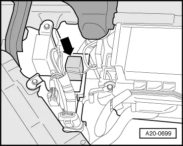
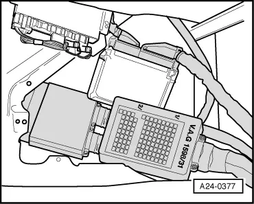
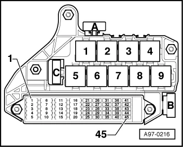
Fuel pump relay -J17 will only close if the engine is turning over. In other words, the relay is only earthed (via the engine control unit) when the engine control unit is receiving engine revolution impulses.

Note:

→ The fuel pump relay is located on the 6-way relay carrier on the left of the driver's footwell, relay position 5.

Test requirement:

  • ● Battery voltage not less than 11 V

Testing operation of fuel pump relay

 
A24-0374
  • ‒ Pull up floor covering in driver's footwell.
  • ‒ → Open cover on electronics box -arrows-.
  • ‒ Start final control diagnosis and activate fuel pump relay -J17:

=> Injection and ignition system; Repair group 01; Final control diagnosis

 
A20-0699
    • ‒ → The fuel pump relay should pick up and the fuel pump should run at intervals. (Relay is located on 6-way relay carrier on left side of driver's footwell, relay position 5).

A - If the relay does not pick up:

  • ‒ Test voltage supply to fuel pump relay.
  • ‒ Test activation of fuel pump relay.

B - If the relay picks up but the fuel pump does not run:

  • ‒ Test voltage supply to fuel pump and other components (via fuel pump relay) .

Testing voltage supply to fuel pump relay

  • ‒ Switch off ignition.
  • ‒ Disconnect fuel pump relay.
 
A24-0298
  • ‒ → Connect multimeter (voltage measurement range) as follows:

6-way relay carrier on left of driver's footwell, relay position 5,
contact

Measure against

2

Engine earth

6

Battery positive

    • ‒ Specification: approx. battery voltage

6-way relay carrier on left of driver's footwell, relay position 5,
contact

Measure against

4

Engine earth

  • ‒ Switch ignition on.
    • ‒ Specification: approx. battery voltage

If a specification is not met:

  • ‒ Check the wiring.

=> Current flow diagrams, Electrical fault finding and Fitting locations binder

  • ‒ Re-insert fuel pump relay.
 
A24-0377

Testing activation of fuel pump relay

  • ‒ Switch off ignition.
  • ‒ → Connect test box V.A.G 1598/31 to control unit wiring harness. The engine control unit remains disconnected .
  • ‒ Bridge contacts 1 and 65 on the test box using test leads from adapter set V.A.G 1594 A.
  • ‒ Switch ignition on.
 
A20-0699
    • ‒ → The fuel pump relay should pick up. (Relay is located on 6-way relay carrier on left side of driver's footwell, relay position 5).

If the relay picks up now but not during the final control diagnosis:

  • ‒ Fit a new engine control unit

=> Injection and ignition system; Repair group 24; Servicing injection system; Replacing engine control unit

If the relay does not pick up:

  • ‒ Switch off ignition.
  • ‒ Disconnect fuel pump relay.
 
A24-0298
  • ‒ → Test for open circuit and short to positive or earth in the following wiring connections:

6-way relay carrier on left of driver's footwell, relay position 5,
Contact

Test box V.A.G 1598/31


Socket

1

65

  • ‒ Rectify any open/short circuit as necessary.

If no fault is found:

  • ‒ Fit a new fuel pump relay -J17.
  • ‒ Reconnect the engine control unit.
 
A97-0216

Testing voltage supply to fuel pump and other components

  • ‒ → Remove fuse Nos. S18, S19 and S245 (sockets 18, 19 and 45) from fuse holder.
  • ‒ Start final control diagnosis and activate fuel pump relay -J17:

=> Injection and ignition system; Repair group 01; Final control diagnosis

  • ‒ For each of the following fuse positions in the fuse holder, connect the multimeter (voltage measurement range) between earth and one of the fuse contacts:

Fuse

Specification
(for one contact)

S18

Approx. battery voltage 1)

S19

Approx. battery voltage 1)

S245

Approx. battery voltage 1)

    1)    at intervals

If the specifications are not obtained:

  • ‒ Repeat the test on the other fuse contact.

If the specifications are again not attained:

  • ‒ Check wiring

=> Current flow diagrams, Electrical fault finding and Fitting locations binder

If no fault is found:

  • ‒ Fit a new fuel pump relay -J17.
  • ‒ Refit fuses.

Checking additional signals > < Adapting engine control unit to throttle valve control part