audi Workshop Repair Guides

Audi Workshop Service and Repair Manuals

Removing and installing high-pressure fuel pump > < Important - Procedure to be followed prior to opening high-pressure injection system
Motronic Direct Injection and Ignition System (4-Cyl.)
Servicing Motronic injection system
Removing and installing intake manifold
Attention:
Fuel system operates under high pressure. Always reduce fuel pressure prior to opening fuel system.
Procedure, see
  • ‒ Remove fresh-air intake duct.

=> Heater and Air Conditioner; Repair Group 80; Checking, removing and installing fresh-air intake duct (in engine compartment)

  • ‒ Remove air duct between air cleaner and air-mass meter using special tool V.A.G 1921 (hose-clamp pliers).
 
A24-0561
  • ‒ Unplug connectors from throttle valve control unit, air-mass meter, potentiometer for exhaust-gas recirculation valve and activated charcoal filter system solenoid valve 1.
  • ‒ → Unscrew and remove the two bolts on fuel lines -arrow- together with activated charcoal filter system solenoid valve 1 from intake manifold.
 
A24-0562
  • ‒ → Disconnect hose from intake connection -1-.
  • ‒ Unbolt exhaust-gas recirculation hose -2-.

 
A24-0563
  • ‒ → Disconnect the two hoses -arrows- from fuel lines.
  • ‒ Disconnect hose from vacuum actuator.
 
A24-0564
  • ‒ → Unplug connector from intake manifold flap air flow control valve -1-, intake manifold flap potentiometer -2- and from intake manifold pressure sender -3-.

 
A24-0565
  • ‒ → Unbolt high-pressure fuel line from high-pressure fuel pump -arrow- and from fuel rail pipe (lower part of intake manifold).
  • ‒ Unscrew all hexagon socket bolts from intake manifold.
 
N13-0438
  • ‒ → Attach support bar 10-222 A using adapters 10-222 A/1.

 
A10-0684
  • ‒ → Remove noise insulation -arrows-.
 
A24-0566
  • ‒ → Unbolt heat shield -arrows-.

 
A24-0567
  • ‒ → Unplug connector from brake servo pressure sensor -1-.
  • ‒ Disconnect hose from crankcase heater -2-.
  • ‒ Unscrew the two bolts -3-.
 
A10-0691
  • ‒ → Unscrew pendulum support -arrows-.

 
A10-0688
  • ‒ → Unscrew the three bolts -2- from engine mount.

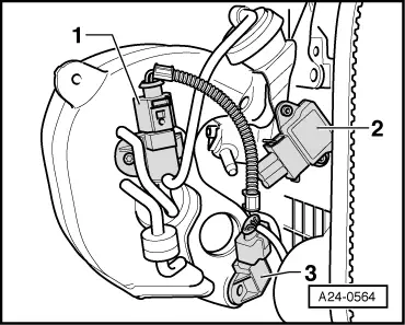
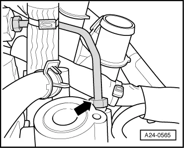
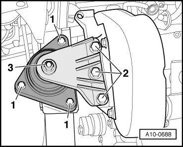
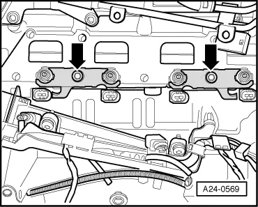
Note:

The central bolt -3- must not be slackened.

  • ‒ Lower engine slightly to remove intake manifold.

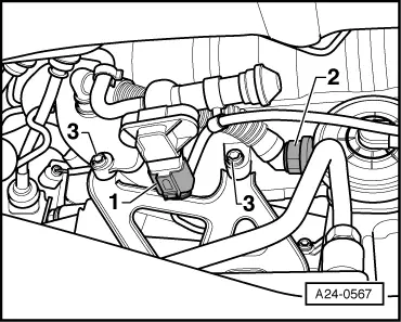
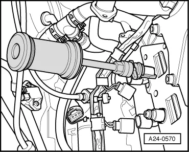
Removing and installing high-pressure injectors

Notes:

 
A24-0568
  • ◆ To improve clarity, the engine is viewed from the rear.
  • ◆ To replace the injectors, you will need the tool box containing the special tool T10133.
  • ‒ → Unscrew the two bolts -arrows-.
  • ‒ Unplug connectors from fuel-pressure sender -1-, from fuel-pressure regulating valve -2-, from intake manifold flap potentiometer -3- and from the four injectors.
 
A24-0569
  • ‒ Unscrew and remove hexagon socket bolts from lower part of intake manifold and carefully pull off lower part of intake manifold (keeping intake manifold parallel).
  • ‒ → Unbolt injector holder -arrows- and remove support piece from injector.

 
A24-0570
  • ‒ → Attach extractor T10133/1 with striker T10133/3 to injector and carefully knock out injector.

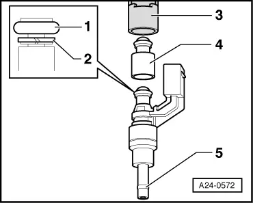
Replacing O-ring and Teflon ring on high-pressure injector

 
A24-0572
  • ● -1- Always replace O-ring
  • ● -2- Only replace support ring if damaged
  • ● -3- Retainer
  • ● -4- Always replace O-ring spacer sleeve
  • ● -5- Always replace Teflon ring

Replacing O-rings

The O-rings from the spacer sleeves and from the high-pressure injector must always be replaced.

  • ‒ Use clean engine oil to facilitate assembly.

Replacing support ring

The support ring only has to be replaced if it has been damaged.

  • ‒ Rotate and pull support ring over collar (do not widen diameter).

Note:

Pay attention to correct installation position. The flat side without shoulder must face the O-ring.

Replacing Teflon ring

The Teflon ring used as a combustion chamber seal must always be replaced if the high-pressure injector is reused.

  • ‒ Carefully remove old Teflon ring using a suitable tool, taking care not to damage groove or continuous ridge in groove land.

Note:

The groove must not be damaged, otherwise the high-pressure injector must be replaced.

 
A24-0571
  • ‒ Sealing ring groove must be cleaned with a clean cloth and any residue must be removed using a brush prior to fitting new Teflon ring.
  • ‒ Use assembly drift (special tool T10133/5) and assembly sleeve T10133/6 to fit new Teflon ring.
  • ‒ → Slide Teflon ring over assembly drift and use assembly sleeve to push Teflon ring into groove of high-pressure injector (do not use any lubrication).

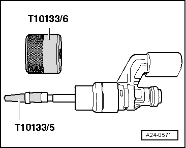
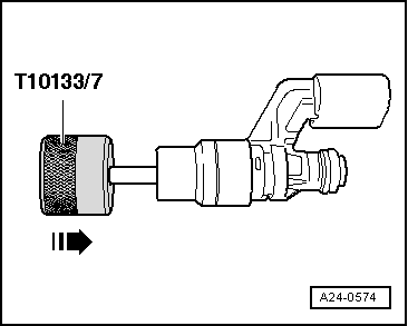
Step 1 of Teflon ring calibration (adaption) is performed using the special tool T 10133/7.

 
A24-0574
  • ‒ → Rotate special tool (approx. 180°) while simultaneously sliding it over injector as far as it will go, applying moderate force. Then pull back to original position, once again rotating by 180°.

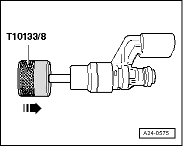
Step 2 of Teflon ring calibration (adaption) is performed using the special tool T 10133/8.

 
A24-0575
  • ‒ → Rotate special tool (approx. 180°) while simultaneously sliding it over injector as far as it will go, applying moderate force. Then pull back to original position, once again rotating by 180°.

 
A24-0573
  • ‒ → Use a nylon brush (special tool T10133/4) to clean high-pressure injector holes in cylinder head (example: cylinder 3).

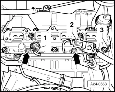
Installing high-pressure injection units and lower part of intake manifold / upper part of intake manifold

Install in reverse order

Important: The following points must always be observed.

 
A24-0599
  • ● High-pressure fuel line must always be replaced.
  • ● Replace all gaskets.
  • ● → Prior to installing lower part of intake manifold, insert a suitable tool through opening of holder and linkage of vacuum actuator to lift intake manifold flaps (otherwise intake manifold flaps cannot be adjusted). Remove tool again when lower part of intake manifold has been installed.
  • ● Adaption of intake manifold flaps must be performed on replacement of lower part of intake manifold (Self-diagnosis, Basic setting, Measured value block 142). Vehicle diagnostic, testing and information system VAS 5051 must be used for this purpose.
  • ● Coat O-rings of high-pressure injection units with clean oil so that they can be inserted into lower part of intake manifold more easily

Torques, see exploded views:

  • ● Removing and installing injection system components
  • ● Dismantling and assembling intake manifold => Page 24-17
  • ● Dismantling and assembling fuel rail with high-pressure injection units => Page 24-25

Removing and installing high-pressure fuel pump > < Important - Procedure to be followed prior to opening high-pressure injection system