|
Notes:
-
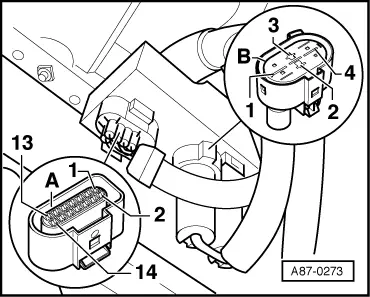
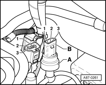
◆ → The compressor will not be switched on if connector -B- is disconnected.
-
◆ High-pressure sensor -A- is an electronic control unit that generates a square-wave signal whose duty cycle changes with refrigerant circuit pressure .
Pin assignment at refrigerant temperature switch -F18 / -F54
Switch -F54 (between contact 1 and 2 closes at approx. 95 °C - the radiator fans are switched to 1st speed).
Switch -F18 (between contact 3 and 2 closes at approx. 102 °C - the radiator fans are switched to 2nd speed).
Note:
In vehicles with map-controlled cooling the radiator fans are switched on and off by the engine control unit dependent on the engine load and the refrigerant temperature (temperature switch -F18/-F54 is not installed).
Test step 1 (voltage supply)
|
|
|---|
|
Select measuring range on hand-held multimeter V.A.G 1526:
Voltage measurement (20V =)
|
|
Test step
|
Contact at connector to -J293
|
Testing of
|
▪ Test conditions
- Additional operations
|
Specified value
|
Remedies if specified value not attained
|
|
1.1
|
Connector B contact 3
and
connector A, contact 6
|
Voltage supply
|
|
- approx. battery voltage
|
- Use current flow diagram to repair power supply and/or earth connection.
|
|
1.2
|
Connector B contact 1
and
connector A, contact 6
|
Voltage supply
|
|
- approx. battery voltage
|
- Use current flow diagram to repair power supply.
|
|
|
|---|
|
Select measuring range on hand-held multimeter V.A.G 1526:
Voltage measurement (20V =)
|
|
Test step
|
Contact at connector to -J293
|
Testing of
|
▪ Test conditions
- Additional operations
|
Specified value
|
Remedies if specified value not attained
|
|
1.3
|
Connector A contact 4
and
connector A, contact 6
|
Voltage supply
|
|
- approx. battery voltage
|
- Use current flow diagram to repair power supply.
|
|
1.4
|
Connector A contact 9
and
connector A, contact 6
|
Voltage supply
|
▪ Ignition on.
|
- approx. battery voltage
|
- Use current flow diagram to repair power supply.
|
Test step 2 (actuation of radiator fan)
Notes:
-
◆ Test steps 2.1, 2.2 and 2.3 are only carried out in vehicles without map-controlled engine cooling.
-
◆ The test step 2.4 is only carried out in vehicles with diesel engine (performance 81 KW) (actuation for radiator fan run out).
-
◆ The test steps 2.5 and 2.6 are only carried out in vehicles with map-controlled engine cooling.
-
◆ In vehicles with map-controlled cooling the radiator fans are switched on and off by the engine control unit dependent on the engine load and the refrigerant temperature (temperature switch -F18/-F54 is not installed).
-
◆ If a fault is found in vehicles with map-controlled engine cooling when the radiator fan is actuated or if the actuation of the fan is to be checked proceed as described in the workshop manual Ignition and Injection system for this engine.
=> Relevant Workshop Manual Injection and Ignition system
|
|
|---|
|
Select measuring range on hand-held multimeter V.A.G 1526:
Voltage measurement (20V =)
|
|
Test step
|
Contact at connector to -J293
|
Testing of
|
▪ Test conditions
- Additional operations
|
Specified value
|
Remedies if specified value not attained
|
|
2.1
|
Connector B contact 2
and
connector A, contact 6
|
"Fan ON" signal (1st speed) from temperature switch -F54.
▪ only to be performed in vehicles without map-controlled cooling
|
▪ Connector detached from temperature switch -F18/-F54, and contacts 1 and 2 jumpered
▪ Ignition on.
|
- approx. battery voltage
Radiator fan running at speed 1
|
- Use current flow diagram to rectify voltage supply to temperature switch -F54.
Use current flow diagram to locate and eliminate open circuit in the wiring between temperature switch -F54 and control unit -J293.
Use current flow diagram to locate and eliminate open circuit in the wiring to fans -V7.
Service radiator fan -V7.
|
|
|
|---|
|
Select measuring range on hand-held multimeter V.A.G 1526:
Voltage measurement (20V =)
|
|
Test step
|
Contact at connector to -J293
|
Testing of
|
▪ Test conditions
- Additional operations
|
Specified value
|
Remedies if specified value not attained
|
|
2.2
|
Connector A contact 7
and
connector A, contact 6
|
"Fan ON" signal (2nd speed) from temperature switch -F18.
▪ only to be performed in vehicles without map-controlled cooling
|
▪ Connector detached from temperature switch -F18/-F54, and contacts 2 and 3 jumpered
▪ Ignition on.
|
- approx. battery voltage
|
- Use current flow diagram to rectify voltage supply to temperature switch -F18.
Use current flow diagram to locate and eliminate open circuit in the wiring between temperature switch -F18 and control unit -J293.
|
Notes:
-
◆ Test step 2.2 is only to be performed in vehicles without map-controlled engine cooling.
-
◆ In vehicles with map-controlled cooling the radiator fans are switched on and off by the engine control unit dependent on the engine load and the refrigerant temperature (temperature switch -F18/-F54 is not installed).
|
|
|---|
|
Select measuring range on hand-held multimeter V.A.G 1526:
Voltage measurement (20V =)
|
|
Test step
|
Contact at connector to -J293
|
Testing of
|
▪ Test conditions
- Additional operations
|
Specified value
|
Remedies if specified value not attained
|
|
2.3
|
Connector A
and
connector B attached to -J293
|
"Fan ON" signal (2nd speed) from temperature switch -F18.
▪ only to be performed in vehicles without map-controlled cooling
|
▪ Connector detached from temperature switch -F18/-F54, and contacts 2 and 3 jumpered
▪ Ignition on.
|
- Radiator fan running at speed 2
|
- Use current flow diagram to locate and eliminate open circuit in the wiring to fans -V7.
Service radiator fan -V7.
Control unit -J293 defective - replace.
|
Notes:
-
◆ The test step 2.3 is only to be performed in vehicles without map-controlled engine cooling.
-
◆ In vehicles with map-controlled cooling the radiator fans are switched on and off by the engine control unit dependent on the engine load and the refrigerant temperature (temperature switch -F18/-F54 is not installed).
|
|
|---|
|
Select measuring range on hand-held multimeter V.A.G 1526:
Voltage measurement (20V =)
|
|
Test step
|
Contact at connector to -J293
|
Testing of
|
▪ Test conditions
- Additional operations
|
Specified value
|
Remedies if specified value not attained
|
|
2.4
|
Connector A contact 11
and
connector A, contact 6
|
Fan on signal (vent run out) from engine control unit.
▪ only to be performed in vehicles with 81 KW diesel engine
|
▪ Ignition on.
Actuate this control element in the final control diagnosis for the engine control unit.
=> Relevant Workshop Manual Diesel Direct Injection and Preglow system
|
- approx. battery voltage during the actuation
|
- Check output at engine control unit.
Use current flow diagram to locate and eliminate open circuit or short to positive or earth in the wiring between -E87 and control unit -J293.
|
|
|
|---|
|
Select measuring range on hand-held multimeter V.A.G 1526:
Voltage measurement (20V =)
|
|
Test step
|
Contact at connector to -J293
|
Testing of
|
▪ Test conditions
- Additional operations
|
Specified value
|
Remedies if specified value not attained
|
|
2.5
|
Connector A contact 11
and
connector A, contact 6
|
Fan on Signal (fan actuation speed 1) from engine control unit.
▪ only to be performed in vehicles with map-controlled engine cooling
|
▪ Ignition on.
Actuate this control element in the final control diagnosis for the engine control unit.
=> Relevant Workshop Manual Injection and Ignition system
|
- approx. battery voltage during the actuation
|
- Check output at engine control unit.
Use current flow diagram to locate and eliminate open circuit or short to earth in the wiring between engine control unit and control unit -J293.
|
Notes:
-
◆ The test step 2.5 is only to be performed in vehicles with map-controlled engine cooling.
-
◆ In vehicles with map-controlled cooling the radiator fans are switched on and off by the engine control unit dependent on the engine load and the refrigerant temperature (temperature switch -F18/-F54 is not installed).
|
|
|---|
|
Select measuring range on hand-held multimeter V.A.G 1526:
Voltage measurement (20V =)
|
|
Test step
|
Contact at connector to -J293
|
Testing of
|
▪ Test conditions
- Additional operations
|
Specified value
|
Remedies if specified value not attained
|
|
2.6
|
Connector A contact 7
and
connector A, contact 6
|
Fan on Signal (fan actuation speed 2) from engine control unit.
▪ only to be performed in vehicles with map-controlled engine cooling
|
▪ Ignition on.
Actuate this control element in the final control diagnosis for the engine control unit.
=> Relevant Workshop Manual Injection and Ignition system
|
- approx. battery voltage during the actuation
|
- Check output at engine control unit.
Use current flow diagram to locate and eliminate open circuit or short to earth in the wiring between engine control unit and control unit -J293.
|
Notes:
-
◆ The test step 2.6 is only to be performed in vehicles with map-controlled engine cooling.
-
◆ In vehicles with map-controlled cooling the radiator fans are switched on and off by the engine control unit dependent on the engine load and the refrigerant temperature (temperature switch -F18/-F54 is not installed).
Test step 3 (actuation of magnetic clutch)
|
Select measuring range on hand-held multimeter V.A.G 1526:
Current measurement (20 A=)
|
|
Test step
|
Contact at connector to -J293
|
Testing of
|
▪ Test conditions
- Additional operations
|
Specified value
|
Remedies if specified value not attained
|
|
3.1
|
Connector A contact 4
and
connector A, contact 10
|
Actuation of air conditioner magnetic clutch -N25
|
▪ Ignition on.
|
- Less than 10 A
Magnetic clutch clicks (when applying voltage)
|
- Use current flow diagram to locate and eliminate open circuit or short to earth in the wiring between control unit -J293 and magnetic clutch -N25.
Open circuit in the earth connection to magnetic clutch -N25.
=> Current Flow Diagrams, Electrical Fault-Finding and Fitting Locations
Magnetic clutch defective - rectify.
|
|
|
|---|
|
Select measuring range on hand-held multimeter V.A.G 1526:
Current measurement (20 A=)
|
|
Test step
|
Contact at connector to -J293
|
Testing of
|
▪ Test conditions
- Additional operations
|
Specified value
|
Remedies if specified value not attained
|
|
3.2
|
Connector A contact 4
and
connector A, contact 12
|
Signal for "Refrigerant circuit pressure OK" to -E87
|
▪ Engine running
▪ The fault reader V.A.G 1551 remains connected.
▪ The self-diagnosis for the air conditioner (address word "08") is initiated.
▪ The display group "001" is selected in the function "read measured value block".
Press "Auto"-key on -E87.
|
- Less than 1 A
"0" is displayed in the measured value block of -E87 (display group "001", display zone "1")
|
- Use current flow diagram to locate and eliminate open circuit or short to positive or earth in the wiring between control unit -J293 and -E87.
Eliminate cause of compressor shutoff condition
|
|
Select measuring range on hand-held multimeter V.A.G 1526:
Current measurement (20 A=)
|
|
Test step
|
Contact at connector to -J293
|
Testing of
|
▪ Test conditions
- Additional operations
|
Specified value
|
Remedies if specified value not attained
|
|
3.3
|
Connector A contact 6
and
connector A, contact 12
|
Signal for "Refrigerant circuit pressure NOK" to -E87
|
▪ Engine running.
▪ The fault reader V.A.G 1551 remains connected.
▪ The self-diagnosis for the air conditioner (address word "08") is initiated.
▪ The display group "001" is selected in the function "read measured value block".
|
- Less than 1 A
"1" is displayed in the measured value block of -E87 (display group "001", display zone "1")
|
- Use current flow diagram to locate and eliminate open circuit or short to positive in the wiring between control unit -J293 and -E87.
|
|
|
|---|
|
Select measuring range on hand-held multimeter V.A.G 1526:
Current measurement (20 A=)
|
|
Test step
|
Contact at connector to -J293
|
Testing of
|
▪ Test conditions
- Additional operations
|
Specified value
|
Remedies if specified value not attained
|
|
3.4
|
Connector A contact 4
and
connector A, contact13
|
Connection to input for "Refrigerant temperature too high" recognition
|
▪ Ignition on.
|
- 0 A
|
- Rectify short circuit to earth in connector A contact 13.
|
Notes:
-
◆ The contact 13 in connector -A- is not occupied in all vehicles. Switching off of the compressor when refrigerant temperature is too high occurs via the operating and display unit -E87 in vehicles in which the contact is not occupied (if the contact is occupied switching off occurs simultaneously via -E87 and -J293).
-
◆ If earth is applied to connector -A- contact 13, the radiator fans are actuated and the compressor is not switched on.
|
Select measuring range on hand-held multimeter V.A.G 1526:
Voltage measurement (20V =)
Bridge at connector A between contact 4 and contact 12
|
|
Test step
|
Contact at connector to -J293
|
Testing of
|
▪ Test conditions
- Additional operations
|
Specified value
|
Remedies if specified value not attained
|
|
3.5
|
Connector A contact 8
and
connector A, contact 6
|
"Compressor ON" signal from -E87
|
▪ Engine running
▪ Operating and display unit -E87 in "auto" mode (compressor on)
|
- approx. battery voltage
|
- Use current flow diagram to locate and eliminate open circuit or short to positive or earth in the wiring between -J293 and -E87.
Eliminate cause of compressor shutoff condition
|
Test step 4 (signal from high-pressure sensor -G65)
|
|
|---|
|
Vehicle diagnosis system VAS 5051 (or commercially available oscilloscope)
"DSO" (digital storage oscilloscope) measurement system
Setting 2V/Div =, 5ms/Div (2 V DC and 5 milliseconds per unit)
|
|
Test step
|
Contact at connector to -J293
|
Testing of
|
▪ Test conditions
- Additional operations
|
Specified value
|
Remedies if specified value not attained
|
|
4.0
|
Connector A contact 2 (signal)
and
connector A, contact 6
(earth)
|
Pressure-dependent square-wave signal from sender -G65
|
▪ Ignition on.
|
- Square-wave signal (dependent on pressure in refrigerant circuit =>Page01-225
|
- Use current flow diagram to check voltage supply and earth connections to High-pressure sensor -G65.
Use current flow diagram to locate and eliminate open circuit in the wiring between High-pressure sensor -G65 and control unit -J293.
|
|
|
|
|
|
|
|
|
|
(cont.)
▼
|
|
|
|---|
|
Vehicle diagnosis system VAS 5051 (or commercially available oscilloscope)
"DSO" (digital storage oscilloscope) measurement system
Setting 2V/Div =, 5ms/Div (2 V DC and 5 milliseconds per unit)
|
|
Test step
|
Contact at connector to -J293
|
Testing of
|
▪ Test conditions
- Additional operations
|
Specified value
|
Remedies if specified value not attained
|
|
4.0
(cont.)
|
|
|
|
|
- Use circuit flow diagram to locate and rectify short circuit in the wiring from -G65 to -J293 or to the engine control unit.
High-pressure sensor -G65 defective - replace.
|
Notes:
-
◆ The signal from high-pressure sensor -G65 depends on pressure in refrigerant circuit
-
◆ The signal generated by high-pressure sensor -G65 is also used for engine control (the required compressor drive torque is governed by the refrigerant circuit pressure). Depending on the engine control unit version, the signal in the measured value block is displayed as duty cycle.
=> Relevant Workshop Manual Injection and Ignition system
Test step 5 (other connections)
|
|
|---|
|
Select measuring range on hand-held multimeter V.A.G 1526:
Voltage measurement (20V =)
|
|
Test step
|
Contact at connector to -J293
|
Testing of
|
▪ Test conditions
- Additional operations
|
Specified value
|
Remedies if specified value not attained
|
|
5.1
|
Connector A contact 5
and
connector A, contact 14
|
Connection via connector A (observe notes).
|
|
- smaller 10 ω(observe note).
|
- Eliminate open circuit or contact resistance.
|
Note:
Connection (bridge) between contacts 5 and 14 at connector A are not present in all types of the control unit -J293.
=> Current Flow Diagrams, Electrical Fault-Finding and Fitting Locations
|
|
|---|
|
Select measuring range on hand-held multimeter V.A.G 1526:
Current measurement (20 A=)
|
|
Test step
|
Contact at connector to -J293
|
Testing of
|
▪ Test conditions
- Additional operations
|
Specified value
|
Remedies if specified value not attained
|
|
5.2
|
Connector A contact 1
and
connector A, contact 4
|
Function of pump for refrigerant run out -V51 (observe note).
|
|
- smaller than 5A (observe note).
|
- Use current flow diagram to locate and eliminate open circuit in the wiring between pump -V51 and control unit -J293.
Pump defective, replace.
|
|
|
|
|
|
- Pump -V51 is running (running noise audible)
|
- Use current flow diagram to locate and eliminate open circuit in the wiring between pump -V51 and control unit -J293.
Locate open circuit in earth wiring to pump -V51 and eliminate.
Pump defective, replace.
|
Note:
The pump for refrigerant run-out -V51 is only present in certain engine variations.
=> Current Flow Diagrams, Electrical Fault-Finding and Fitting Locations
=> Relevant Workshop Manual Injection and Ignition system
|