A3 Mk1
| Diagram of connections for charge pressure control system and vacuum system |
| Vehicles with engine codes APY, AUL |
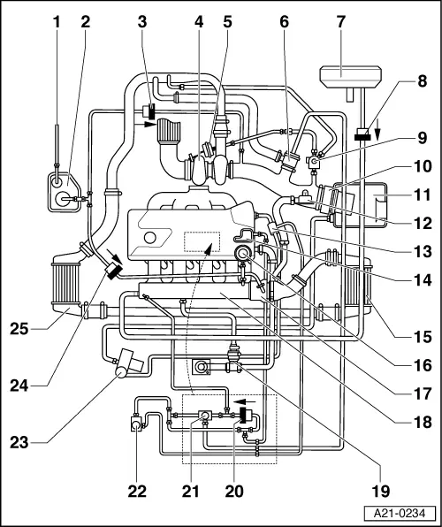
| 1 - | From fuel tank |
| 2 - | Activated charcoal filter |
| q | With activated charcoal filter system solenoid valve 1 -N80- |
| 3 - | Non-return valve |
| q | Between activated charcoal filter and intake pipe upstream of turbocharger |
| q | Installation position: arrow points direction of flow |
| 4 - | Turbocharger |
| q | Checking charge pressure → Chapter |
| 5 - | Vacuum unit for charge pressure control |
| 6 - | Mechanical air recirculation valve |
| q | Checking → Chapter |
| 7 - | Brake servo |
| 8 - | Non-return valve |
| q | Between brake servo and intake manifold |
| q | Installation position: arrow points direction of flow |
| 9 - | Charge pressure control solenoid valve -N75- |
| q | Checking → Chapter |
| 10 - | Air mass meter -G70- |
| 11 - | Air cleaner |
| 12 - | Pressure control valve for crankcase breather system |
| 13 - | Combination valve for secondary air system |
| 14 - | Vacuum reservoir |
| q | Bolted to cylinder head cover |
| 15 - | Charge air cooler |
| q | With charge pressure sender -G31- |
| q | Checking charge pressure sender -G31- → Chapter |
| 16 - | Fuel pressure regulator |
| 17 - | Throttle valve module -J338- |
| 18 - | Intake manifold |
| q | With intake air temperature sender -G42- |
| 19 - | Crankcase breather |
| 20 - | Non-return valve |
| q | Installation position: arrow points direction of flow |
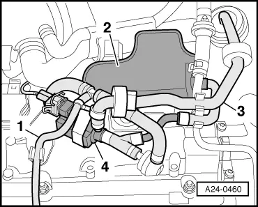
| 21 - | Turbocharger air recirculation valve -N249- |
| q | Fitting location → Fig. |
| q | Checking → Chapter |
| 22 - | Secondary air inlet valve -N112- |
| q | Checking → Chapter |
| 23 - | Secondary air pump motor -V101- |
| 24 - | Non-return valve |
| q | Between activated charcoal filter and intake manifold |
| q | Installation position: arrow points direction of flow |
| 25 - | Charge air cooler |
| Vehicles with engine code AMK, BAM |

| 1 - | From fuel tank |
| 2 - | Activated charcoal filter |
| q | With activated charcoal filter system solenoid valve 1 -N80- |
| 3 - | Non-return valve |
| q | Between activated charcoal filter and intake pipe upstream of turbocharger |
| q | Installation position: arrow points direction of flow |
| 4 - | Turbocharger |
| q | Checking charge pressure → Chapter |
| 5 - | Vacuum unit for charge pressure control |
| 6 - | Mechanical air recirculation valve |
| q | Checking → Chapter |
| 7 - | Brake servo |
| 8 - | Non-return valve |
| q | Between brake servo and intake manifold |
| q | Installation position: arrow points direction of flow |
| 9 - | Charge pressure control solenoid valve -N75- |
| q | Checking → Chapter |
| 10 - | Air mass meter -G70- |
| 11 - | Air cleaner |
| 12 - | Pressure control valve for crankcase breather system |
| 13 - | Vacuum reservoir |
| q | Bolted to cylinder head cover |
| 14 - | Charge air cooler |
| q | With charge pressure sender -G31- |
| q | Checking charge pressure sender -G31- → Chapter |
| 15 - | Fuel pressure regulator |
| 16 - | Throttle valve module -J338- |
| 17 - | Intake manifold |
| q | With intake air temperature sender -G42- |
| 18 - | Crankcase breather |
| 19 - | Non-return valve |
| q | Installation position: arrow points direction of flow |
| 20 - | Turbocharger air recirculation valve -N249- |
| q | Fitting location → Fig. |
| q | Checking → Chapter |
| 21 - | Non-return valve |
| q | Between activated charcoal filter and intake manifold |
| q | Installation position: arrow points direction of flow |
| 22 - | Charge air cooler |