| –
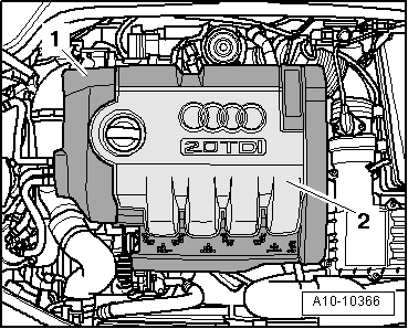
| Install engine cover panel -1 and 2-. |
| –
| If a new control unit has been fitted, it must be encoded. |
| To do so, use the vehicle diagnosis, testing and information system -VAS 5051 x - or -VAS 5052-. |
| –
| Connect vehicle diagnosis, testing and information system and select „function/component“ for function test → Chapter. |
| –
| „01 - Self-diagnosis compatible systems“ |
| –
| „J104 - Control unit for ABS/TCS/ESP Mark 60“ |
| –
| „J104 - Control unit for ABS/TCS/ESP, Functions“ |
| –
| „J104 - Encoding control unit“ |
| –
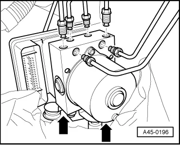
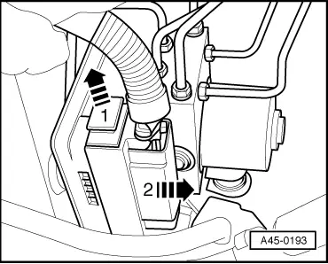
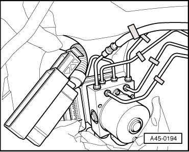
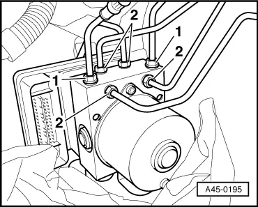
| Perform final control diagnosis after attaching brake lines to hydraulic unit. Vehicle diagnosis, testing and information system -VAS 5051 x - or -VAS 5052- |

Note | t
| If the ABS control unit (with ESP) -J104- is renewed, the following senders must be calibrated: |
| t
| Steering angle sender -G85- |
| t
| Lateral acceleration sender -G200- |
| t
| Brake pressure sender 1 -G201- |
| t
| Longitudinal acceleration sender -G251- (only four-wheel drive vehicles) |
| t
| From model year 2009 onwards, steering angle and brake pressure are also measured by the ABS control unit (with ESP) -J104-; these values must then be calibrated. |
| t
| ESP road test and system test must then be carried out. |
| To do so, use the vehicle diagnosis, testing and information system -VAS 5051 x - or -VAS 5052-. |
| –
| Connect -VAS 5051 x - or -VAS 5052- and select „function/component“ for function test → Chapter. |
| –
| „01 - Self-diagnosis compatible systems“ |
| –
| „J104 - Control unit for ABS/TCS/ESP Mark 60“ |
| –
| „J104 - Control unit for ABS/TCS/ESP, Functions“ |
| On vehicles with Mark 60EC system |
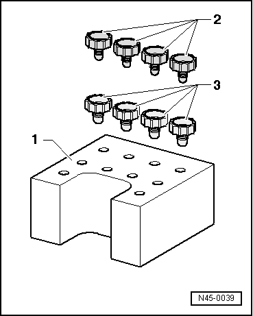
| If the ABS control unit -J104- is renewed on vehicles with Mark 60EC system, an additional basic setting must be performed for the inlet valves and separating valves → Chapter. |
| To do so, use the vehicle diagnosis, testing and information system -VAS 5051 x - or -VAS 5052-. |
Note | Final control diagnosis can be used to establish whether line connections have been interchanged. |
|
|
|


 WARNING