| Flushing (cleaning) refrigerant circuit with refrigerant R134a |
| Vehicles with high-voltage system (hybrid vehicles) |

WARNING | Safety hazard: the engine can start unexpectedly. |
| Before carrying out general work on a vehicle with high-voltage electrical system, switch off the ignition and remove the ignition key from the vehicle. |
|
WARNING | Working on vehicles with high-voltage wiring: |
| l
| Do not support yourself or tools on high-voltage wiring or associated components --> this can damage the insulation. |
| l
| High-voltage wiring must not be excessively bent or kinked --> this can damage the insulation. |
| l
| The round high-voltage connectors are colour-coded with an external coloured ring and are provided with mechanical coding or guide lugs. It is important to observe this coding when joining up the round high-voltage connectors, otherwise the connectors can be damaged. |
|
DANGER! | Risk of fatal injury if high-voltage components are damaged. |
| Observe the following when working in the vicinity of high-voltage components or wiring: |
| t
| It is not permitted to use cutting or forming tools, other sharp-edged tools or heat sources such as welding, brazing, soldering, hot air or thermal bonding equipment. |
| t
| Before starting work, visually inspect the high-voltage components in the areas involved. |
| t
| Before working in the engine compartment, visually inspect the power electronics -JX1-, electric drive motor -V141-, air conditioner compressor -V470- and high-voltage wiring. |
| t
| Before working on the vehicle underbody, visually inspect the high-voltage wiring and covers. |
| t
| Before working on the rear section of the vehicle, visually inspect the high-voltage wiring and the electro-box with the maintenance connector for high-voltage system - TW -. |
| t
| Visually inspect all potential equalisation lines. |
| Check the following when making the visual inspection: |
| t
| There must be no external damage on any component. |
| t
| The insulation of the high-voltage wiring and potential equalisation lines must not be damaged. |
| t
| There must be no unusual deformation of the high-voltage wiring. |
| t
| All high-voltage components must be identified by a red warning sticker. |
|
| If work is necessary in the vicinity of high-voltage system components, perform a visual inspection of the high-voltage components and wiring to check for damage → Chapter and note → Electrical system; Rep. gr.93. |
| De-energising high-voltage system |
DANGER! | Voltage can cause fatal injury. |
| Danger of severe or fatal injuries from electric shock. |
| t
| For reasons of safety, persons with life-preserving or other electronic medical devices in or on their body must not perform any work on the high-voltage system. Such medical devices include internal analgesic pumps, implanted defibrillators, pacemakers, insulin pumps and hearing aids. |
| t
| The high-voltage system may only be de-energised by a suitably qualified person (Audi high-voltage technician). |
| t
| It must be definitely confirmed that the high-voltage system is de-energised. The system may only be de-energised using the vehicle diagnostic tester via „Guided Fault Finding“. |
| t
| The qualified person (Audi high-voltage technician) confirms that the system is de-energised and uses the locking cap -T40262- to ensure that the system cannot be re-energised. The ignition key and the maintenance connector for high-voltage system - TW - should then be stored in a safe place by the qualified person. |
| t
| The qualified person (Audi high-voltage technician) marks the vehicle by attaching the appropriate warning signs. |
|

Note | t
| De-energising high-voltage system: |
| t
| Connect vehicle diagnostic tester |
| t
| Select Guided Fault Finding mode |
| t
| Using the Go to key, select the following menu items in succession |
| t
| Function/component selection |
| t
| Self-diagnosis compatible systems |
| t
| 8C - Hybrid battery management -J840 |
| t
| 8C - Hybrid battery management, functions |
| t
| 51 - De-energise high-voltage system (Rep. gr. 93) |
| Re-energising high-voltage system |
DANGER! | Voltage can cause fatal injury. |
| Danger of severe or fatal injuries from electric shock. |
| t
| For reasons of safety, persons with life-preserving or other electronic medical devices in or on their body must not perform any work on the high-voltage system. Such medical devices include internal analgesic pumps, implanted defibrillators, pacemakers, insulin pumps and hearing aids. |
| t
| The high-voltage system may only be re-energised by a suitably qualified person (Audi high-voltage technician). |
| t
| The system may only be re-energised using the vehicle diagnostic tester via „Guided Fault Finding“. |
| t
| The vehicle is then made ready for operation again by the qualified person (Audi high-voltage technician). |
| t
| The qualified person (Audi high-voltage technician) marks the vehicle by attaching the appropriate warning signs. |
|
Note | t
| Re-energise high-voltage system: |
| t
| Connect vehicle diagnostic tester |
| t
| Select Guided Fault Finding mode |
| t
| Using the Go to key, select the following menu items in succession |
| t
| Function/component selection |
| t
| Self-diagnosis compatible systems |
| t
| 8C - Hybrid battery management -J840 |
| t
| 8C - Hybrid battery management, functions |
| t
| 51 - Re-energise high-voltage system (Rep. gr. 93) |
DANGER! | When working on a vehicle with the ignition switched on or while the drive system is active, the engine can start unexpectedly and exhaust fumes can cause a health hazard in closed rooms. Moving parts can trap or draw in parts of the body and/or clothing (safety hazard). |
| Before switching on the ignition, perform the following steps: |
| t
| Move selector lever to position P |
| t
| Connect battery charger (e.g. -VAS 5095A-) to jump-start connections of 12 V electrical system |
|
| –
| For test and measurement work that requires the vehicle's drive system to be active or the ignition to be switched on, move the selector lever to position „P“, activate the parking brake and arrange the tools needed so that they cannot come into contact with moving components of the engine and so that they cannot even come near to components that turn when the engine is running. |
Note | t
| Move the selector lever to position „P“ and activate the parking brake before performing test and measurement work for which the ignition must be switched on but where the vehicle's drive system does not need to be active. |
| t
| The status of the drive system is shown by the control unit in dash panel insert -J285- via the „power meter“ → Owner's Manual. |
| t
| Activating and deactivating drive system → Owner's Manual (note display of control unit in dash panel insert -J285-). |

Caution | t
| If there is a possibility that chemical substances (sealing additives) for sealing leaks have been added to the refrigerant circuit to be flushed, do not connect the air conditioner service station to this refrigerant circuit and do not flush this refrigerant circuit. |
| t
| Chemical substances (sealing additives) for sealing leaks form deposits in the refrigerant circuit which will impair operation of the air conditioning system and lead to failure of the system (and of the air conditioner service station). |
| t
| Customers should be informed that the air conditioner in their vehicle contains substances not approved by Audi and that the system can therefore not be flushed and serviced by your workshop. |
|
Note | t
| Audi does not permit the use of chemical substances (sealing additives) to seal leaks in the refrigerant circuit. |
| t
| Chemical substances (sealing additives) for sealing leaks in the refrigerant circuit generally react with the ambient air or the humidity contained in it. They cause malfunctioning of valves and other components with which they come into contact on account of deposits in the refrigerant circuit (and in the air conditioner service station being used). These deposits cannot be completely removed from the components affected (even by flushing). The refrigerant circuit can therefore only be repaired by renewing all the components which have come into contact with this substance. |
| t
| Chemical substances (sealing additives) for sealing leaks in the refrigerant circuit are normally not outwardly apparent and the identification stickers which should be affixed for this purpose are usually non-existent. Vehicles with an unknown history should therefore be treated with due caution. |
| l
| The best way of removing moisture, impurities (e.g. abrasion from a defective air conditioner compressor) and old refrigerant oil without any unnecessary loss of refrigerant and without extensive assembly work, whilst at the same time ensuring environmental compatibility, is to flush the refrigerant circuit with refrigerant R134a. |
| The refrigerant circuit is to be flushed: |
| –
| In there is any dirt or similar in the circuit. |
| –
| If vacuum reading is not maintained on evacuating a leak-free refrigerant circuit (pressure build-up due to moisture in refrigerant circuit) |
| –
| If the refrigerant circuit has been left open for longer than the normal assembly time (e.g. following an accident). |
| –
| If pressure and temperature measurements in the refrigerant circuit indicate the likelihood of moisture. |
| –
| If there are doubts about the amount of refrigerant oil in the refrigerant circuit. |
| –
| If the air conditioner compressor has to be renewed on account of internal damage (e.g. noise or no output). |
| –
| If stipulated by the vehicle-specific workshop manual following replacement of certain components. |
| t
| Air conditioner service station with flushing attachment (these air conditioner service stations feature the additional function „Flushing refrigerant circuit“ and the necessary flushing attachment for refrigerant circuits) → Workshop equipment and special tools catalogue |
Note | t
| Use can be made for vehicles with screw connections at the refrigerant circuit of the adapter -V.A.G 1785/7- and adapter -V.A.G 1785/8- from the VW/Audi passenger vehicle adapter set -VAS 6338/1-. Two adapters -V.A.G 1785/8- are required for a vehicle with screw connections at the air conditioner compressor and reservoir. |
| t
| The adapter set for refrigerant circuits -VAS 6338/1- also contains a short filler hose -VAS 6338/31- with 5/8 -18 UNF connections and a large inside diameter (commercially available). |
| –
| Discharge the refrigerant circuit → Chapter. |
| Vehicle with restrictor and reservoir |
Note | It would be possible to flush the reservoir, however on account of its large internal volume it holds too much liquid refrigerant. On extracting this refrigerant, the reservoir would ice up severely, the refrigerant would only evaporate very slowly and the extraction process would be excessively long. |
| Vehicle with expansion valve and receiver |
Note | t
| In the case of condensers with an integrated receiver / dryer cartridge which cannot be renewed separately or which are not available separately, the condenser is to be renewed after flushing. On these vehicles, the condenser is then to be renewed together with the receiver → Heating, air conditioning; Rep. gr.87 and → Electronic parts catalogue. |
| t
| Depending on the version, receivers on which the dryer cartridge can be renewed separately may be provided with an additional filter element which may have to be renewed together with the dryer cartridge. |
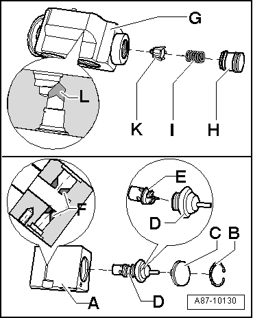
Note | If there is no suitable adapter for the expansion valve in the VW/Audi passenger vehicle adapter set -VAS 6338/1-, the expansion valve removed can also be drilled open (the old expansion valve generally has to be renewed and is therefore no longer needed). |
Caution | t
| Take care not to damage the sealing surfaces at the expansion valve when drilling it open. |
| t
| Otherwise, refrigerant will escape at damaged sealing surfaces. |
|
Note |
|
|