audi Workshop Repair Guides

Audi Workshop Service and Repair Manuals

Removing and installing heat exchanger > < Removing and installing heat exchanger of air conditioning unit (heater)
Preparation for heat exchanger removal
–  Place protective covers over driver's and front passenger's seats.
–  Switch off ignition.
–  Dissipate the pressure in the coolant circuit by opening the cap at the coolant expansion tank. → Engine, mechanics; Rep. gr.19
   
–  Remove any components impeding access to the coolant hoses to the heat exchanger in the engine compartment -A- and -B- → Engine, mechanics; Rep. gr.13.
  Note
t  Depending on the engine and vehicle model, it may be necessary to unfasten or remove the following components: Top engine cover, compressed air pipe to throttle valve unit and intake manifold etc. → Engine, mechanics; Rep. gr.13.
  A87-0674
t  Depending on the engine (e.g. on certain 2.0 l diesel engines depending on the exhaust system design), it may be necessary to remove the plenum chamber cover and the front wall of the plenum chamber -A- in order to be able to remove the heat shield and detach the refrigerant lines from the expansion valve as well as the coolant hoses to the heat exchanger → General body repairs, exterior; Rep. gr.55.
t  On right-hand drive vehicles, the glove compartment and the control motor for the temperature flap attached to the left of the air distribution housing have to be removed instead of the driver's storage compartment → General body repairs, interior; Rep. gr.68 and → Chapter.
t  On vehicles with 5-cyl. engine, remove the air pipe (from the air cleaner to the turbocharger) → Injection and ignition system; Rep. gr.24.
  A87-10683
t  There are different versions of the heat shield -B-. With version „1“, it is not necessary to remove the speed nuts -A- and to detach the heat shield -B- from the vehicle (the coolant hoses can be detached even with the heat shield fitted).
  A87-10273
t  With version „2“, the clamping washers -A- and the clip -C- have to be removed and the heat shield -B- detached from the vehicle.
t  For greater clarity, the illustrations show the heat shield -B- with the engine removed.
–  If fitted and if applicable, detach the heat shield -B- from the front wall of the plenum chamber and the bulkhead and lay it aside (or remove it completely).
  A80-10000
–  If fitted, slide back the thermal insulation -D- and -E- so as to permit attachment for example of the hose clamps up to 40 mm -3093--F- to the coolant hoses -A- and -B-.
  A87-10269
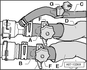
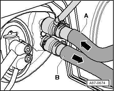
–  Mark the positions of the coolant hoses -A- and -B-.
  Note
t  The heat exchanger is designed for a certain coolant flow direction. Care must therefore be taken to connect the coolant hoses correctly (coolant hose -A-: supply from cylinder head, coolant hose -B-: return to coolant pump).
t  The arrangement of the coolant hoses is identical for vehicles without air conditioner (heater only) and with air conditioner. This illustration shows the layout on a vehicle with air conditioner.
t  Bleeding coolant circuit → Engine, mechanics; Rep. gr.13.
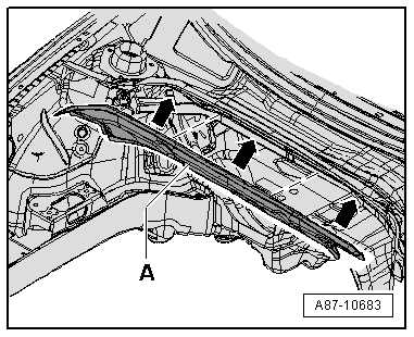
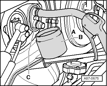
–  If necessary, pinch off the breather hose (from the top connection -A- to the coolant expansion tank).
–  Cover the area beneath the connections for the coolant hoses -A- and -B- with absorbent paper, for example.
–  Pinch off the coolant hoses to the heat exchanger of the air conditioning unit (heater) (e.g. using hose clamps up to dia. 40 mm -3093-) and detach the hoses.
  A87-0674
–  Attach a section of tubing -A- to the top connection.
–  Hold a vessel -B- beneath the bottom connection -C-.
–  Use a compressed-air gun to carefully blow the coolant out of the heat exchanger (into the vessel -B-).
  A87-0675
–  Remove the bolt -A- from the connecting flange -B- (so that the coolant pipes can be moved for removal of the heat exchanger).
–  Remove the driver's storage compartment: → General body repairs, interior; Rep. gr.68
–  Remove the centre console. → General body repairs, interior; Rep. gr.68
  A87-0683
–  Remove the left footwell vent -A- (driver side). → General body repairs, interior; Rep. gr.68
–  Remove the holder -B- → General body repairs, interior; Rep. gr.68.
–  On vehicles with electric supplementary heater (vehicles with diesel engine only), remove the supplementary air heater element -Z35- (together with the supplementary air heater control unit -J604-) → Chapter.
  A87-0684

Removing and installing heat exchanger > < Removing and installing heat exchanger of air conditioning unit (heater)