audi Workshop Repair Guides

Audi Workshop Service and Repair Manuals

Block diagram of air distribution system > < Preparation for heat exchanger removal
Removing and installing heat exchanger
Removing
–  Perform preparatory work for heat exchanger removal → Chapter.
   
–  Remove the 4 bolts -A- and detach the cover -B-.
  Note
t  The illustration shows the version of the air conditioning unit with electric supplementary heater.
  A87-0685
t  
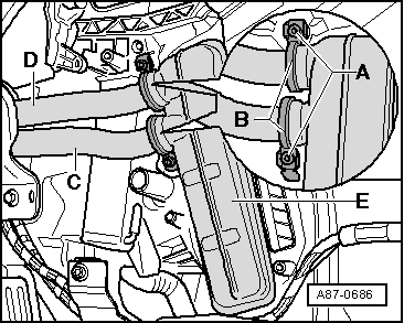
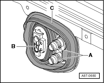
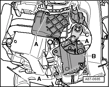
There are different versions of the cover -B- (for vehicles without or with electric supplementary heater).
t  
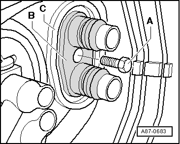
If the lever -C- (to the left temperature flap) is positioned such that the upper bolt -A- is not accessible, switch on the ignition and select a different temperature setting (e.g. on the operating and display unit, Climatronic control unit -J255- the setting „Hi“ for the left side / on the air conditioner controls, air conditioning system control unit -J301-, the setting „Rotary temperature switch on warm stop“).
–  Protect the floor covering in the area beneath the heat exchanger with impermeable sheeting and absorbent paper.
  A87-0685
–  Remove the bolts -A- and detach the clips -B- from the connections of the coolant pipes -C- and -D- at the heat exchanger -E-.
–  Detach the coolant pipes -C- and -D- from the heat exchanger -E- (slide the coolant pipes towards the bulkhead).
–  Pull the heat exchanger -E- out of the air conditioning unit (heater).
Installing
Install in reverse order, paying attention to the following:
  A87-0686
–  Check the seals -A- and -B- attached to the heat exchanger. Only fit a heat exchanger with intact seals.
  Note
t  The seal may curl up on insertion if not correctly bonded on.
t  Cold air may flow past the heat exchanger if the seal is damaged or not properly fitted.
  A87-0687
t  As of Model Year 2005, additional foam strips -A- are bonded to the corners of the heat exchanger -B-. These foam strips -A- are designed to prevent the rattling noise which may occur in particular on vehicles with diesel engine. These strips are to be affixed to all heat exchangers (e.g. self-adhesive foam with part number 191 819 069 → Electronic parts catalogue).
  A87-10134
–  With the heat exchanger removed, check the air conditioning unit (heater) for contamination (by way of the slot -A- for the heat exchanger).
–  Remove any dirt or remnants of escaped coolant from the air conditioning unit (heater) e.g. after removing a leaking heat exchanger.
–  Slide the heat exchanger into the air conditioning unit (heater).
  A87-0688
–  Remove the old clips -B- from both coolant pipes -C-.
–  Attach new clips -A- (included in scope of delivery of heat exchanger) to both heat exchanger coolant pipes as shown.
–  Moisten the new seals -A- (included in scope of delivery of heat exchanger) slightly with coolant.
–  Insert the new seals -A- in the connections of the heat exchanger -D-.
–  Press both coolant pipes -C- into the connections of the heat exchanger -D-.
–  Re-check the position of the seals -A- between the coolant pipes -C- and the connections of the heat exchanger -D-.
  A87-0689
–  Attach the two coolant pipes -C- and -D- with clips -B- to the heat exchanger.
–  Tighten the bolts at the clips -A- to 2.5 Nm.
  A87-0686
–  Check the position of both clips -B- after tightening the bolts -A-. The clips must completely surround the flange at the heat exchanger and coolant pipe and not make contact with other components.
  A87-0686
–  Fit the bolt -A- in the connecting flange -B- (in doing so, make sure the bolt really is screwed in at the intended attachment point).
  A87-0683
–  Check that the grommet -C- is correctly positioned in the bulkhead.
–  If necessary, apply silicone adhesive sealant to the flanges for the coolant pipes to the heat exchanger -A- and the expansion valve (to the evaporator) -B- at the lead-throughs of the grommet -C- (to prevent the ingress of water).
  A87-0680
–  Connect the coolant hoses to the heat exchanger correctly. Note the markings:
A - Supply from cylinder head
B - Return to coolant pump
–  Re-install the components removed in reverse order with the exception of the cover for the connections at the heat exchanger and the driver's storage compartment.
–  Check the installation position of the coolant hoses to the heat exchanger (they must not make contact with components which become warm) as well as the position and condition of the thermal insulation which may be attached to the coolant hoses (not fitted with all types of engine).
–  Bleed the coolant circuit: →  Engine, mechanics; Rep. gr.19
  Note
t  When bleeding the coolant circuit, take special care to ensure complete bleeding of the heat exchangers. If air bubbles remain in the heat exchanger, complaints may be received about a lack of heat output in winter or differences in the temperature of the air flowing out of the vents with the same setting in control mode → Chapter.
t  Depending on the vehicle equipment and the engine, the coolant hoses may be provided with thermal insulation. This must not be damaged and must be re-attached following installation.
  A87-0674
–  Check the coolant circuit for leaks, paying particular attention to the connection between the coolant pipes and the heat exchanger. →  Engine, mechanics; Rep. gr.19
Check the coolant circuit for leaks e.g. as follows:
t  Bleed the coolant circuit. →  Engine, mechanics; Rep. gr.19
t  Carefully open the cap at the coolant expansion tank (heed the safety precautions for opening the cap) → Engine, mechanics; Rep. gr.19.
t  Use the cooling system tester -V.A.G 1274/- hand pump for example to increase the pressure in the coolant circuit.
–  Re-install the cover for the connections at the heat exchanger, the driver's storage compartment and the other components removed.
  A87-0686

Block diagram of air distribution system > < Preparation for heat exchanger removal