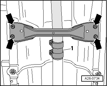
| –
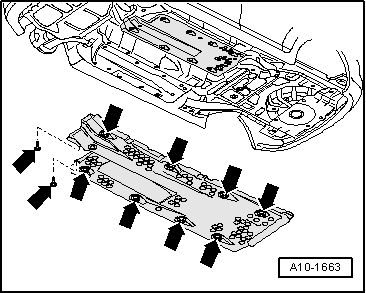
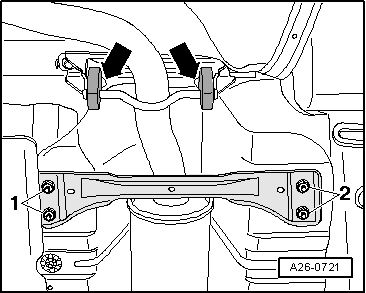
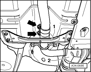
| Remove rear tunnel cross-piece -1-. |
| –
| Take up weight of front section of exhaust system at catalytic converter using engine/gearbox jack -V.A.G 1383 A-. |

Note | To prevent damage, the flexible couplings in the front exhaust pipe must not be bent further than 10°. |
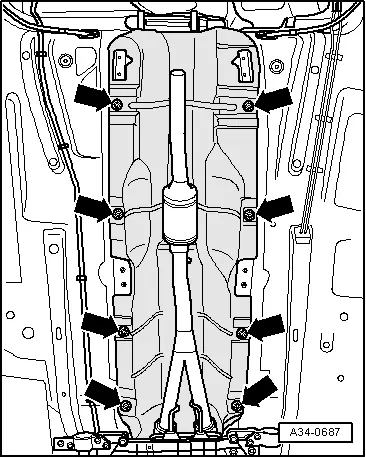
| –
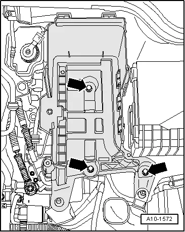
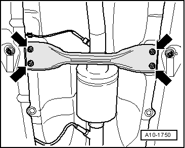
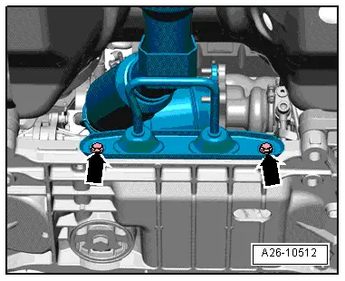
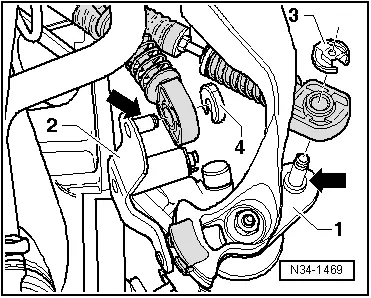
| Disconnect exhaust system at clamp -arrows-. |
Note | A second mechanic is required for removing the rear section of the exhaust system. |
| –
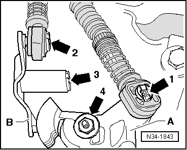
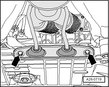
| Detach rear silencer -2- at rubber mountings and remove rear section of exhaust system. |
| –
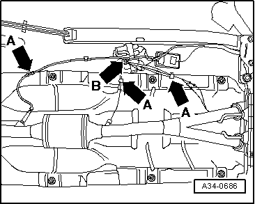
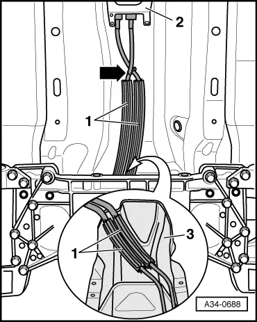
| Lower front section of exhaust system slightly using engine and gearbox jack -V.A.G 1383 A- (not more than 10°). Make sure there is sufficient clearance for Lambda probe wiring. |
|
|
|

 WARNING