audi Workshop Repair Guides

Audi Workshop Service and Repair Manuals

Removing and installing gearbox on vehicles with 2.0 ltr. FSI engine > < Removing gearbox
Installing gearbox
Installing gearbox
Installation is carried out in reverse sequence; note the following:
Please note the information in the table below - „Checking gear oil level and filling up with gear oil“.
   
„Checking gear oil level and filling up with gear oil“
  »No«»Yes«»Yes«
GearboxReplacement unitX  
No oil escapingX  
Was completely dismantled X
Before installing → Item
Oil capacity → Chapter
 
Was partially dismantled
l  (gearbox housing and clutch housing were not separated)
  X
After installing → Chapter

  Note
t  The special tools required are listed in the procedure for → Chapter „Removing gearbox“.
t  Renew self-locking nuts and bolts when performing assembly work.
t  Renew oil seals and gaskets, and bolts which are tightened by turning through a specified angle.
t  Secure all hose connections with the correct hose clips (as original equipment); refer to → Electronic parts catalogue.
t  Re-attach all cable ties at the same locations when re-installing.
t  Clean input shaft splines and (in the case of used clutch plates) the hub splines. Remove corrosion and apply only a very thin coating of grease for clutch plate splines -G 000 100- to the splines. Then move clutch plate backwards and forwards on input shaft until hub moves freely on shaft. It is important to remove excess grease.
   
–  Check that dowel sleeves -A- for centralising engine/gearbox are in the cylinder block; install any missing dowel sleeves.
If the dowel sleeves are not fitted, this will lead to gear-change problems, clutch malfunction and in some cases gearbox noise (gears will make rattling noises).
  A34-0683
–  Make sure that the intermediate plate is engaged on the sealing flange and fitted on the dowel sleeves -arrows-.
–  Check clutch release bearing for wear and renew if necessary.
–  Lubricate surface which contacts ball-head pin with grease for clutch plate splines -G 000 100-.
  A10-0129
–  Incline gearbox via spindles of gearbox support -3282-.
l  The differential must face upwards.
l  Pivot gearbox downwards in area of 6th gear.
–  Then raise gearbox carefully.
  A34-0719
–  Guide gearbox with differential past subframe -A- and swivel in direction of -arrow-.
–  Make sure longitudinal member -B- is not in the way.
  N34-11129
l  Guide flange shaft (right-side) -1- past recess -arrow- in intermediate plate.
–  Align gearbox with engine in installation position and install.
–  Bolt gearbox onto engine. Tightening torques → Anchor
–  Detach gearbox jack with gearbox support -3282- from gearbox after bolting gearbox to engine.
–  Remove engine support -3300 A- and support -T10036-.
–  Install starter → Electrical system; Rep. gr.27.
  N34-11127
–  Secure gearbox bracket -A- to gearbox with new bolts -arrows-. Tightening torque → Item
–  Pull gearbox up to support arm of gearbox mounting with spindle on support bracket -10 - 222 A-.
  N34-1847
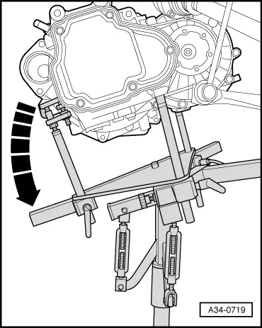
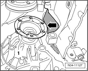
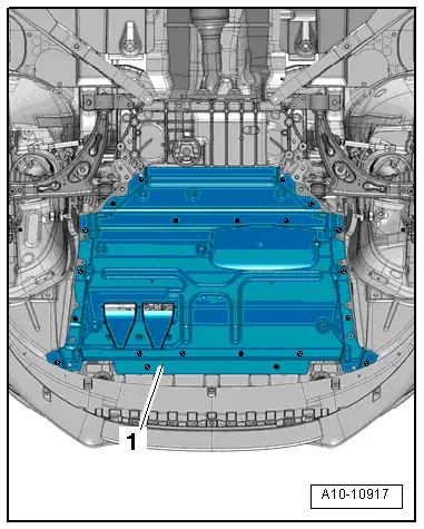
–  Align engine/gearbox in installation position. To do so, raise engine/gearbox until gearbox bracket makes full contact with gearbox mounting.
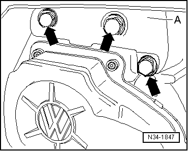
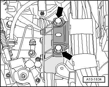
  Caution
The threads in the gearbox bracket can be damaged if the bolts are not inserted straight.
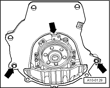
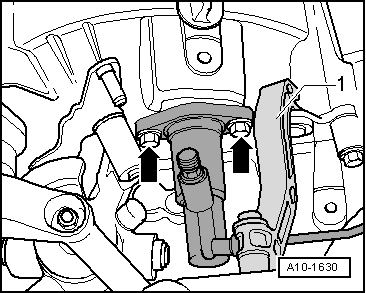
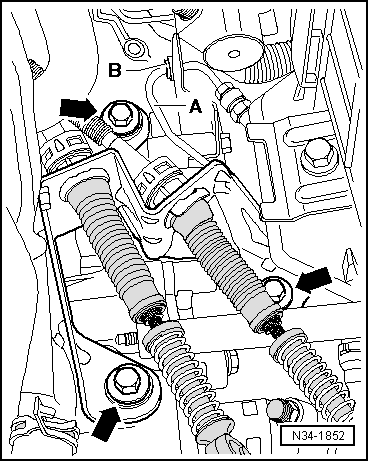
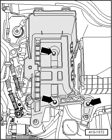
Before fitting the bolts -arrows-, the gearbox bracket and the support arm of the gearbox mounting must be aligned absolutely parallel. If necessary, press rear part of gearbox up with engine and gearbox jack.
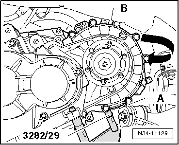
–  Use new bolts -arrows- to secure gearbox mounting to gearbox bracket. Tightening torque → Item
  WARNING
Do not remove support bracket -10 - 222 A- until all bolts securing the left-hand engine/gearbox mounting have been tightened to the specified torque.
–  Check mountings of engine/gearbox assembly for correct adjustment → Engine, mechanics; Rep. gr.10.
  A10-1634
–  Fit pendulum support with new bolts -1 … 3- in accordance with installation instructions → Anchor. Tightening torques → Chapter
  A10-1578
–  Secure catalytic converter to turbocharger -arrows- → Engine, mechanics; Rep. gr.26.
  Note
-Item 1- and -item 2- can be disregarded.
  A26-10130
–  Install radiator cowl -arrows- and attach electrical connector -1-.
  A19-0473
–  Install air intake hose. Make sure retaining clip -arrow- snaps onto retaining lug -A-.
–  Secure drive shafts to flange shafts on gearbox → Running gear, front-wheel drive and four-wheel drive; Rep. gr.40.
–  Secure heat shield for drive shaft (right-side) to engine.
  N21-0184
–  Install clutch slave cylinder -arrows-. Tightening torque → Item
–  Install gearbox support -1-. Tightening torque → Item
  A10-1630
–  Gearbox for vehicles with start/stop system: plug connector -arrow- into gearbox neutral position sender -G701-.
  N34-11243
–  Plug in electrical connector -arrow- at reversing light switch -F4-.
–  Connect earth strap at upper engine/gearbox securing bolt.
  N34-10682
Metal gate relay lever -B-:
  Note
To install, lubricate bearings and moving surfaces with grease -G 000 450 02-.
–  Install gearbox selector lever -A- → Fig..
–  Tighten hexagon nut -arrow 4- to specified torque → Item.
–  Fit gate relay lever -B- and secure with securing clip -arrow 3-.
–  Attach gear selector cable to gearbox selector lever and secure with securing clip -arrow 1-.
–  Attach gate selector cable to gate relay lever and secure with securing clip -arrow 2-.
  N34-1843
Plastic gate relay lever:
–  Insert gate relay lever with cable end-piece as far as stop.
l  Gate relay lever is secured by detent -arrow 1-.
l  Ensure that components engage securely.
l  Cable end-piece must be behind detent -arrow 2-.
  Note
From 08.2008 onwards the gate relay lever is secured with a clip → Fig..
  N34-10889
Continued for all vehicles:
–  Secure cable support bracket -arrows-. Tightening torque → Item
–  Fit bracket -B- to gearbox.
–  Push pipe/hose assembly -A- into bracket -B- on gearbox.
–  Adjust selector mechanism → Chapter.
  N34-1852
–  Install battery tray -arrows- and battery → Electrical system; Rep. gr.27.
–  Install air cleaner housing → Rep. gr.24.
–  Install engine cover panel → Engine, mechanics; Rep. gr.10.
  A10-1572
–  Install front section of wheel housing liner (left-side) → General body repairs, exterior; Rep. gr.66.
–  Fit front left wheel → Rep. gr.44.
  A10-1566
Audi A3
–  Install noise insulation (centre) -1 and 2- → General body repairs, exterior; Rep. gr.50.
  A10-10761
Audi A3 Cabriolet
–  Install noise insulation frame -arrow- → General body repairs, exterior; Rep. gr.50.
  A10-11037
–  Install noise insulation (centre) -1- → General body repairs, exterior; Rep. gr.50.
  A10-10917
Tightening torques
Engine/gearbox attachment (1.8 ltr. TFSI engine)
  A34-0683
ItemBoltNm
1, 2M12 x 6580
3 1)2)M12 x 15080
4 1)2)M12 x 16580
5M10 x 5040
6M12 x 8580
ADowel sleeves for centralising
l  1) Bolt with stud M8.
l  2) Also starter to gearbox

   
ComponentNm
Clutch pipe bracket to gearbox20
Bracket for electrical wiring at bottom starter bolt23
Heat shield for drive shaft to cylinder block25


Removing and installing gearbox on vehicles with 2.0 ltr. FSI engine > < Removing gearbox