audi Workshop Repair Guides

Audi Workshop Service and Repair Manuals

Installing gearbox > < Removing and installing gearbox on vehicles with 2.0 ltr. FSI engine
Removing gearbox
   
Removing gearbox
Special tools and workshop equipment required
t  Support bracket -10 - 222 A-
t  Gearbox support -3282-
t  Pin -3282/29-
t  Adjustment plate -3282/39-
t  Engine and gearbox jack -V.A.G 1383 A-

   
t  Press tool -T10148-
  W00-1277
t  Spindle from assembly device -3066- or M8 x 105 bolt
t  Grease for clutch plate splines -G 000 100-
  Note
All cable ties which are released or cut open during removal must be fitted in the same position when installing.
  Caution
When disconnecting the battery there is a risk of serious damage to electronic components:
Observe the correct procedure for disconnecting the battery → Electrical system; Rep. gr.27.
  W00-10499
–  Press release tab -arrow- and remove cover -1- over battery.
  A10-1611
–  With ignition switched off, disconnect earth wire -arrow- at battery.
  A10-1612
–  Disconnect hose -1- and connector -2- at air cleaner housing.
–  Remove bolt -3-.
–  Release spring clips -4- and detach air intake hose.
–  Take out air cleaner housing.
–  Remove battery → Electrical system; Rep. gr.27.
  A10-1613
–  Remove battery tray -arrows-.
–  Detach front of battery tray from air duct.
  A10-1572
–  Unplug electrical connectors -1- at starter and -4- at reversing light switch -F4-.
–  Unscrew wire -2- at starter and earth wire -3-.
–  Move wiring clear.
–  Remove top starter mounting bolt.
  A27-0204
–  Detach cable support bracket from gearbox -arrows-.
–  Remove bracket -B- from gearbox and disconnect from pipe/hose assembly -A-.
  N34-1852
Metal gate relay lever -B-:
–  Detach securing clip -arrow 1- from gearbox selector lever -A- and pull off gear selector cable.
–  Detach securing clip -arrow 2- from gate relay lever -B- and pull off gate selector cable.
–  Pull off securing clip -arrow 3- and remove gate relay lever -B-.
  N34-1843
Plastic gate relay lever
–  Detach securing clip -arrow 1- and pull off gear selector cable.
–  Detach gate selector cable from cable end-piece → Anchor.
–  Press detent -arrow 2- down onto stop and remove gate relay lever together with cable end-piece. Move gate relay lever in normal direction of operation.
  Note
From 08.2008 onwards the gate relay lever is secured with a clip → Fig..
Continued for all vehicles:
–  Tie cables with cable support bracket to one side.
–  Remove nut -arrow 3- and detach gearbox selector lever -A-.
  N34-11108
–  Remove gearbox support -arrows A-.
–  Remove clutch slave cylinder -arrows B-, move to one side and secure with wire. Do not disconnect pipes.
  WARNING
Do not depress clutch pedal after removing slave cylinder.
–  Remove upper engine/gearbox securing bolts.
  N34-1844
–  Remove engine cover panel -arrows-.
  A10-1709
–  Position support bracket -10 - 222 A- on wing mounting flanges with adapters -10 - 222 A /3-. Spindles face to the front.
–  Take up weight of engine evenly with both spindles; do not lift.
–  Raise vehicle.
–  Remove front left wheel.
–  Turn steering to the left.
  A34-0679
–  Remove centre noise insulation (fasteners -1 ... 3-).
  A10-1565
–  Remove front section of wheel housing liner (left-side) → General body repairs, exterior; Rep. gr.66.
  A10-1566
–  Gearbox for vehicles with start/stop system: unplug connector -arrow- from gearbox neutral position sender -G701-.
  N34-11243
–  Remove nut -2- and detach bracket -1- from stud together with electrical wiring.
–  Remove bottom starter mounting bolt and take out starter.
  A27-0205
–  Unbolt heat shield for right-side drive shaft -arrows-.
–  Unbolt drive shafts (left and right) from gearbox flange shafts.
–  Lift drive shafts as far as possible and tie in place. Do not damage surface coating.
  Note
The left drive shaft should be tied up as far forward as possible.
  A10-1633
–  Unbolt support bracket for exhaust system -arrows-.
  A10-1632
–  Remove bolts -1 ... 3- and detach pendulum support.
  A10-1578
–  Remove hexagon bolts -arrows- at left mounting from gearbox mounting.
  N34-1846
–  Adjust spindles of support bracket -10 - 222 A- to lower gearbox by distance -a-.
l  Dimension -a- = 50 mm
  A34-0580
–  Unbolt gearbox bracket -A- from gearbox -arrows-.
  N34-1847
–  Remove bolts -A- and -B- and take out strut -1-.
  A34-0680
–  Remove securing bolt -arrow- for flange shaft. To do this, screw two bolts into flange and counterhold flange shaft with suitable lever.
  Note
Before removing flange shaft, check oil seal for damage. A leaking oil seal must be renewed when fitting flange shaft.
–  Pull out flange shaft and spring.
  A34-0691
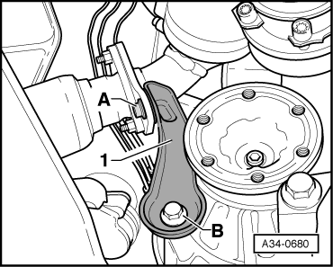
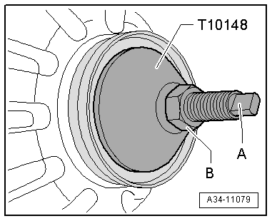
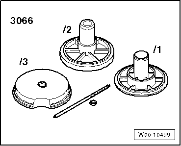
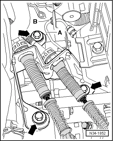
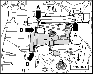
–  Screw spindle -A- of assembly device -3066- into threaded piece in differential.
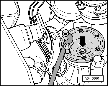
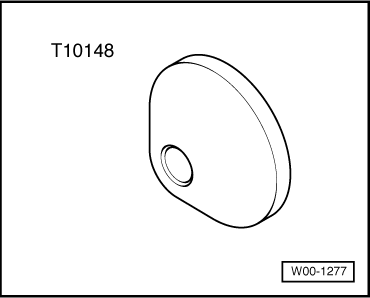
–  Insert thrust piece -T10148- and secure with nut -B-.
  Note
t  The thrust piece -T10148- serves to protect the oil seal (right-side) and the gearbox from dirt.
t  Instead of using the spindle -A-, an M8 x 105 mm bolt can also be screwed hand-tight into the threaded piece in the differential.
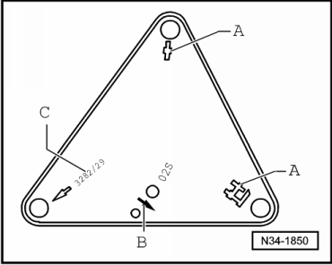
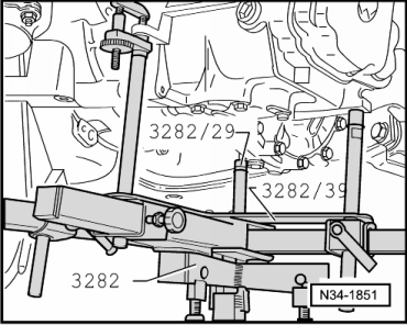
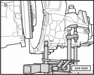
To remove gearbox „02S“, set up gearbox support -3282- with adjustment plate -3282/39-.
–  Insert gearbox support -3282- in engine and gearbox jack -V.A.G 1383 A-.
–  Align arms of gearbox support according to holes in adjustment plate.
  A34-11079
–  Bolt on support elements -A- and -C-, as illustrated on adjustment plate.
–  Place engine and gearbox jack -V.A.G 1383 A- under vehicle; arrow symbol -B- on adjustment plate points to front of vehicle.
  N34-1850
–  Align adjustment plate parallel to gearbox and lock safety support on gearbox.
–  Remove bottom engine/gearbox connecting bolts.
  N34-1851
–  Carefully pull gearbox off dowel sleeves.
t  Distance between gearbox and engine is slightly greater at the front than at the back.
  A34-0024
–  Push gearbox forwards slightly and bring it into the position shown.
–  Lower gearbox out of vehicle. When removing gearbox, ensure sufficient clearance between sleeve -1- and pressure plate -arrow- to prevent damage.
  Note
  A34-0681
If you will be installing a new gearbox instead of the one removed, re-install flange shaft and tighten countersunk bolt -arrow-. Tightening torque → Item
  A34-0682

Installing gearbox > < Removing and installing gearbox on vehicles with 2.0 ltr. FSI engine