audi Workshop Repair Guides

Audi Workshop Service and Repair Manuals

Assembly mountings - exploded view > < Transporting gearbox
Installing gearbox
Installing gearbox
Installation is carried out in reverse sequence; note the following:
  Note
t  Renew seals, gaskets and self-locking bolts and nuts.
t  Renew bolts which are tightened by turning through a specified angle.
t  Secure all hose connections with the correct hose clips (as original equipment); refer to → Electronic parts catalogue.
t  All cable ties which are released or cut open during removal must be fitted in the same position when installing.
t  Clean input shaft splines and (in the case of used clutch plates) the hub splines. Remove corrosion and apply only a very thin coating of grease -G 000 100- to the splines. Then move clutch plate backwards and forwards on input shaft until hub moves freely on shaft. It is important to remove excess grease.
t  It should be possible to push the clutch plate back and forth slightly on the input shaft.
t  If the dowel sleeves are not fitted, this will lead to gear-change problems, clutch malfunction and in some cases gearbox noise (gears will make rattling noises).
   
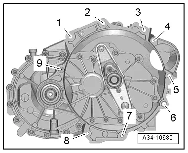
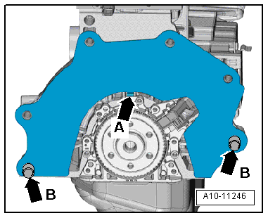
Vehicles with 1.2 ltr. TFSI engine:
–  Check that dowel sleeves -A- for centralising engine/gearbox are in the cylinder block; install any missing dowel sleeves.
  A34-10685
–  Engage intermediate plate at sealing flange -arrow A- and push onto dowel sleeves -arrows B-.
  A10-11246
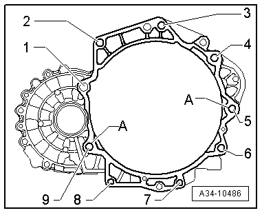
Vehicles with 1.4 ltr. TFSI engine:
–  Check that dowel sleeves -A- for centralising engine/gearbox are in the cylinder block; install any missing dowel sleeves.
  A34-10486
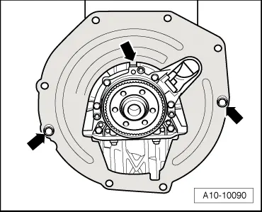
–  Make sure that the intermediate plate is engaged on the sealing flange and fitted on the dowel sleeves -arrows-.
Continued for all vehicles:
–  Check release bearing for wear and renew if necessary.
–  Lubricate surface on release lever which contacts ball-head pin with MoS2 grease.
  A10-10090
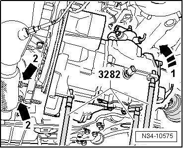
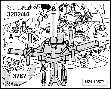
–  Raise gearbox carefully and move to installation position using gearbox support -3282-.
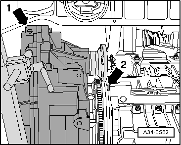
–  When doing this, carefully guide gearbox, as illustrated, past flywheel -arrow 2- and subframe -arrow 1-.
  A34-0582
–  Turn gearbox in area of cover for 6th gear upwards as illustrated -arrow 1-.
–  Then pivot differential side of gearbox downwards and move gearbox into installation position.
l  Gearbox must be aligned parallel to engine.
–  Fit gearbox and and tighten bolts -arrows 2-. Tightening torque: vehicles with 1.2 ltr. TFSI engine → Anchor, vehicles with 1.4 ltr. TFSI engine → Anchor.
  N34-10575
–  Screw in and tighten engine/gearbox securing bolt -A-. Tightening torque: vehicles with 1.2 ltr. TFSI engine → Anchor, vehicles with 1.4 ltr. TFSI engine → Anchor.
–  Remove gearbox support -3282-.
–  Bolt gearbox onto engine.
  N34-10572
Tightening torques for engine/gearbox connection (1.2 ltr. TFSI engine):
  A34-10685
ItemBoltNm
1, 2, 3M12x6080
4 1)M12x5580
5 2)M12x15080
6M12x7080
7, 8M10x3040
9M12x8080
ADowel sleeves for centralising
l  1) Starter to gearbox
l  2) Also starter to gearbox
l  3) Cover plate to gearbox

   
Tightening torques for engine/gearbox connection (1.4 ltr. TFSI engine):
  A34-10486
ItemBoltNm
1, 2, 3M12×5080
4
Bolt with stud M8
M12×5580
5
Bolt with stud M8
M12x15080
6, 9M12×6080
7, 8M10x5040
ADowel sleeves for centralising

   
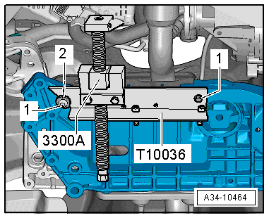
–  Remove engine support -3300 A- and support -T10036-.
  A34-10464
–  Bolt gearbox bracket to gearbox using new bolts -arrows 2-. Tightening torque → Chapter „Assembly mountings - exploded view“
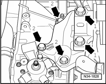
–  Raise engine and gearbox and secure to gearbox mounting with new bolts -arrows 2-. Follow correct tightening sequence → Fig.. Tightening torque → Chapter „Assembly mountings - exploded view“
  N34-1828
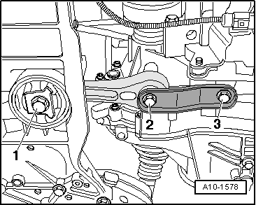
–  Bolt pendulum support onto gearbox first, and then secure to subframe -bolts 1 ... 3-.
–  Use new bolts. Tightening torque → Chapter „Assembly mountings - exploded view“
  Note
Install engine/gearbox mountings stress-free → Rep. Gr.10.
  A10-1578
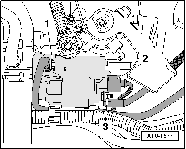
–  Install starter → Electrical system; Rep. Gr.27.
–  Secure earth wire -1- and wiring -2- and -3-.
  A10-1577
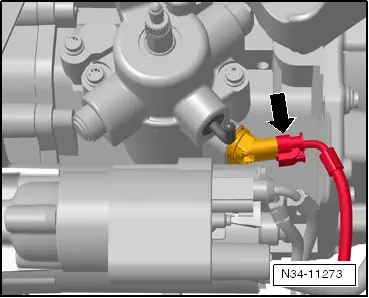
Vehicles with start/stop system:
–  Attach connector -arrow- for gearbox neutral position sender -G701-.
  N34-11273
Continued for all vehicles:
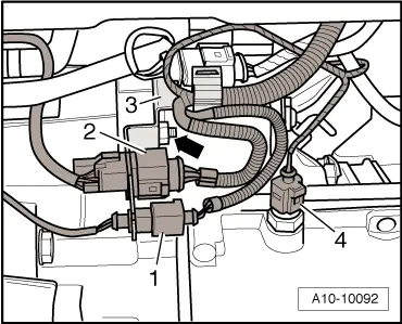
–  Secure bracket -3- together with electrical wiring -1- and -2-.
–  Attach connector -4- for reversing light switch -F4-.
–  Bolt drive shafts to flange shafts → Running gear, front-wheel drive and four-wheel drive; Rep. Gr.40..
–  Install exhaust system and ensure stress-free alignment → Engine, mechanics; Rep. Gr.26..
  A10-10092
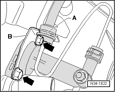
–  Install clutch slave cylinder -arrows -. Tightening torque → Item
–  Engage hose/pipe assembly -A- on bracket -B-.
  N34-1822
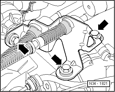
–  Install cable support bracket on gearbox and tighten bolts -arrows-. Tightening torque → Item
  N34-1821
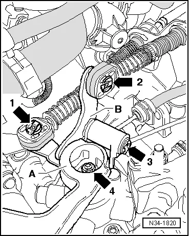
–  Install gearbox selector lever -A-. Installation position → Item.
–  Tighten new hexagon nut -arrow 4-. Tightening torque → Item
–  Fit gate relay lever -B- in bearing on selector mechanism cover.
–  When doing so, pivot gate relay lever so that slide block -C- engages in guide on gearbox selector lever.
–  Secure gate relay lever with securing clip -arrow 3-.
–  Apply a small amount of grease -G 000 450 02- to pins of gearbox selector lever -A- and gate relay lever -B-.
–  Secure gear selector cable -arrow 1- and gate selector cable -arrow 2-.
–  Adjust selector mechanism → Chapter.
–  Install engine cover panel → Injection and ignition system; Rep. Gr.24.
–  Fill up oil in gearbox and check oil level → Chapter.
–  Install noise insulation.
–  Install battery tray and battery → Electrical system; Rep. Gr.27.
–  Install air cleaner housing → Injection and ignition system; Rep. Gr.24.
  N34-1820

Assembly mountings - exploded view > < Transporting gearbox