audi Workshop Repair Guides

Audi Workshop Service and Repair Manuals

Removing and installing pendulum support > < Exploded view - assembly mountings
Removing and installing gearbox mounting
Special tools and workshop equipment required
   
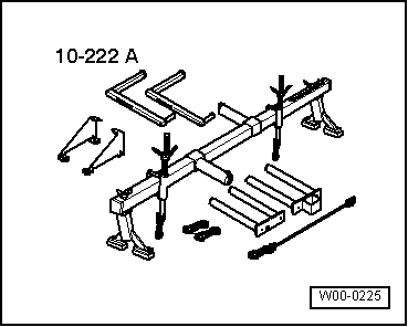
t  Support bracket -10 - 222 A-
  W00-0225
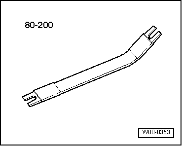
t  Removal lever -80 - 200-
  W00-0353
Removing
–  Shift selector lever into position “P”.
–  Switch off ignition.
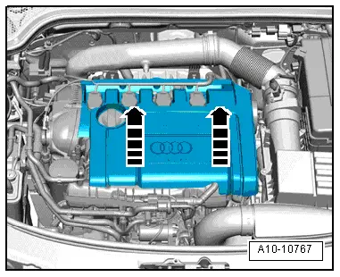
Vehicles with 1.8 ltr. TFSI engine:
–  Remove engine cover panel -arrows-.
–  Remove air cleaner housing → Injection and ignition system; Rep. Gr.24.
  A10-10767
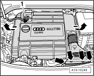
Vehicles with 2.0 ltr. TFSI engine:
–  Unplug electrical connector -1- from air mass meter -G70-.
–  Unclip air intake connection -bottom arrows-.
–  Remove engine cover panel -top arrows-.
  A10-10249
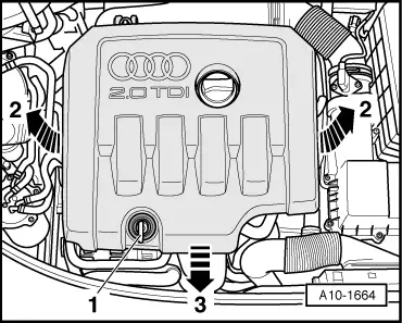
Vehicles with TDI engine (unit injector):
–  Lift engine cover panel at the sides -arrows 2- and pull out from the front -arrow 3-.
–  Remove air cleaner housing → Injection and glow plug system; Rep. Gr.23.
  A10-1664
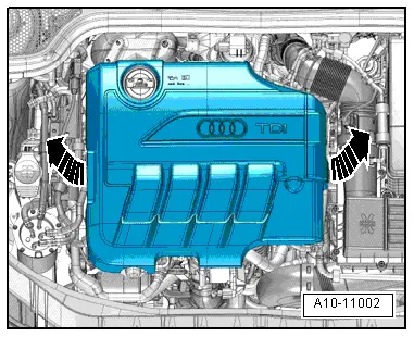
Vehicles with TDI engine (common rail):
–  Remove engine cover panel -arrows-.
–  Remove air cleaner housing → Injection and glow plug system; Rep. Gr.23.
  A10-11002
Continued for all vehicles:
  Caution
When disconnecting the battery there is a risk of serious damage to electronic components:
Observe the correct procedure for disconnecting the battery.
–  Remove battery → Electrical system; Rep. Gr.27.
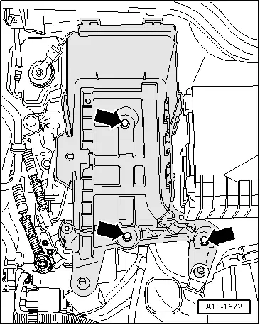
–  Remove bolts -arrows- and detach battery tray.
–  Detach bonnet seal at lock carrier and at wing flanges.
  A10-1572
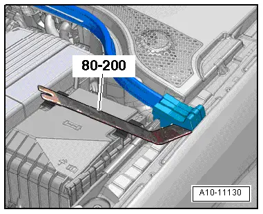
–  If necessary, lever clip off sealing element using removal lever -80 - 200- and fold up sealing element.
  A10-11130
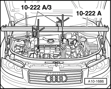
–  Set up support bracket -10 - 222 A- on wing mounting flanges (vehicles up to 05.2008) or on body flanges (vehicles from 05.2008 onwards), as shown in illustration.
  Note
Diagram shows 2.0 ltr. TDI engine.
–  If there are hoses and wire connections in area of engine lifting eyes for support bracket -10 - 222 A-, remove these now.
–  Engage spring hooks of spindles on lifting eyes.
–  Take up weight of engine/gearbox assembly via the spindle, but do not raise.
  A10-1686
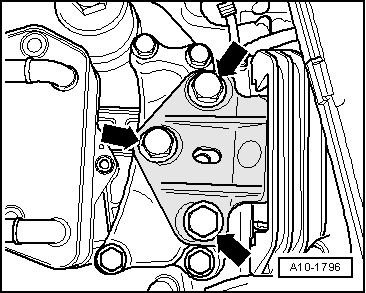
–  Unscrew bolts -arrows- to release the gearbox support from the gearbox mounting.
–  Lower engine/gearbox assembly slightly via the spindle.
  A10-1796
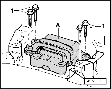
–  Remove all components which prevent access to bolts -1-.
–  Remove bolts -1-.
–  Take off gearbox mounting -A-.
Installing
Installation is carried out in reverse sequence; note the following:
l  Tightening torques → Chapter „Exploded view - assembly mountings“
  Note
Renew bolts which are tightened by turning through a specified angle.
–  Install gearbox mounting -A-.
–  Secure gearbox mounting with new bolts -1-.
  A37-0685
–  Pull gearbox up with spindle on support bracket until gearbox support contacts support arm of gearbox mounting.
  Caution
Before tightening the bolts -arrows-, the gearbox support and the support arm of the gearbox mounting must be aligned absolutely parallel, otherwise the threads will be damaged. If necessary, push gearbox up at the rear with trolley jack.
–  Check mountings of engine/gearbox assembly for correct adjustment → Engine, mechanics; Rep. Gr.10.
–  Bolt support arm of gearbox mounting onto gearbox support using new bolts -arrows-.
–  Install battery tray and battery → Electrical system; Rep. Gr.27.
–  Install air cleaner housing → Injection and glow plug system; Rep. Gr.23 or → Injection and ignition system; Rep. Gr.24.
  A10-1796

Removing and installing pendulum support > < Exploded view - assembly mountings