
A3 Mk2
 Note
Note
|
| Component | Nm | |
| Bolts/nuts | M6 | 9 |
| M7 | 15 | |
| M8 | 22 | |
| M10 | 40 | |
| M12 | 65 | |
|
|
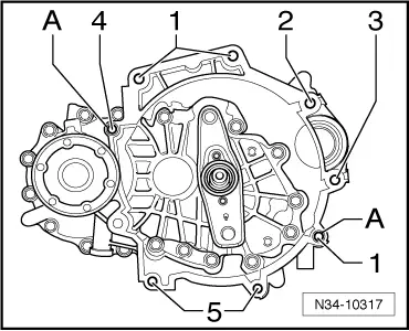
| Item | Bolt | Nm | ||
| 1 | M12x65 | 80 | ||
| 2 1) | M12x135 | 80 | ||
| 3 1) | M12x150 | 80 | ||
| 4 | M12x80 | 80 | ||
| 5 | M10x50 | 40 | ||
| A | Dowel sleeves for centralising | |||
| ||||
|
|
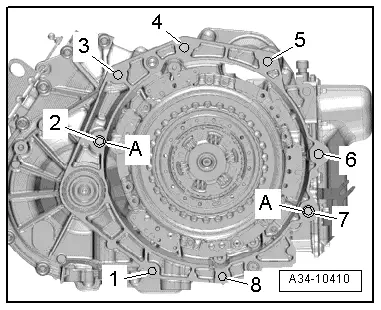
| Item | Bolt | Nm |
| 1, 8 | M10x50 | 40 |
| 2, 6, 7 | M12x65 | 80 |
| 3, 4, 5 | M12x55 | 80 |
| A | Dowel sleeves for centralising | |
Note
|
|
|
|
|
|
|
Note
|
|
|
|
Note
|
|
Note
|
|
 Caution