
A3 Mk2
| Removing and installing cylinder head |
| Special tools and workshop equipment required |
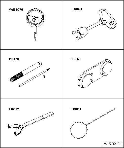
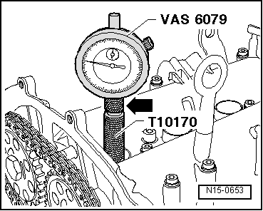
| t | Dial gauge -VAS 6079- |
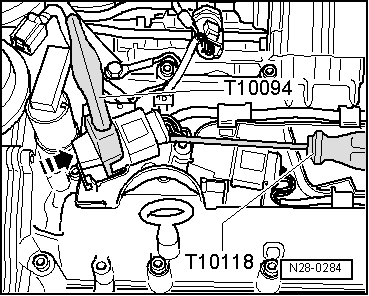
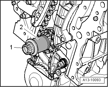
| t | Puller -T10094- |
| t | Adapter for dial gauge -T10170- |
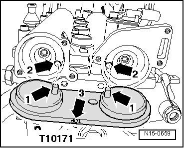
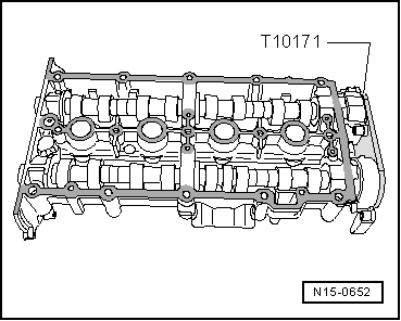
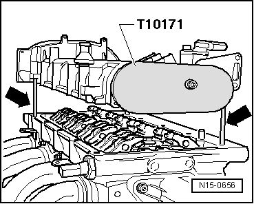
| t | Camshaft clamp -T10171- |
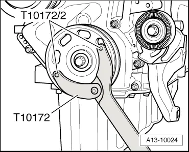
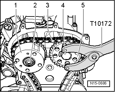
| t | Counterhold tool -T10172- |
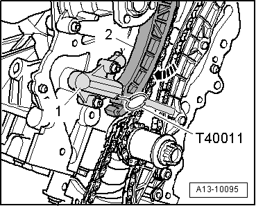
| t | Locking pin -T40011- |
|
|
|
|
|
|
 WARNING
|
|
|
|
|
|
|
|
|
|
|
|
|
|
|
|
|
|
|
|
 Note
Note
|
|
Note
|
|
|
|
Note
|
|
|
|
|
|
|
|
|
|
|
|
|
|
|
|
Note
|
|
|
|
|
|
|
|
|
|
 Caution
|
|
Note
|
|
Note
|
|
|
|
|

|
|
|
Note
|
|
|
|
Note
|
|
|
|
|
Note
|
|
|
|
|
Note
|
|
Note
|
|
|
|
|
|
|
|
| Component | Nm | |||||||
| Camshaft adjuster to camshaft | 40 + 90° 1)2)3) | |||||||
| Camshaft sprocket to camshaft | 50 + 90° 2)3) | |||||||
| Spark plugs in cylinder head | 30 | |||||||
| Sealing caps to camshaft housing | 10 | |||||||
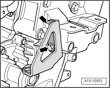
| Engine lifting eye to timing chain cover | 20 | |||||||
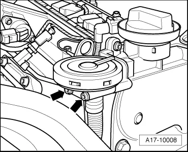
| Pressure control valve for crankcase breather system to timing chain cover | 10 | |||||||
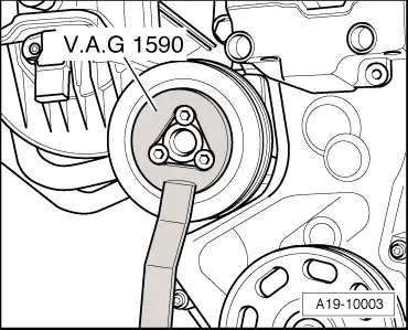
| Coolant pump pulley to coolant pump | 20 | |||||||
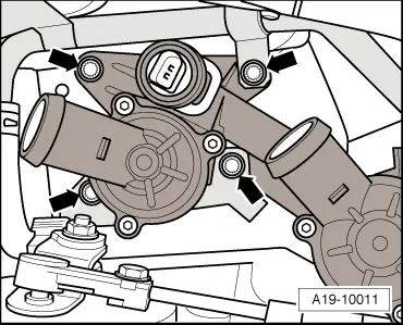
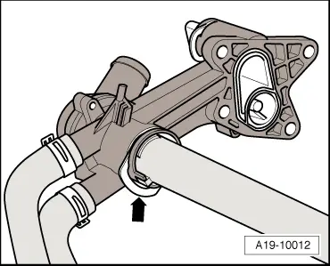
| Thermostat housing to cylinder head | 10 | |||||||
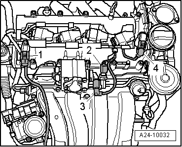
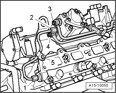
| High-pressure pipes | High-pressure pump | 15 | ||||||
| to: | Fuel rail | 15 | ||||||
| High-pressure pump bracket | 7 | |||||||
| EGR connecting pipe to exhaust gas recirculation valve -N18- | 8 | |||||||
| Throttle valve module -J338- to intake manifold | 7 | |||||||
| ||||||||