
A3 Mk2
| Removing and installing timing chain cover |

| Special tools and workshop equipment required |
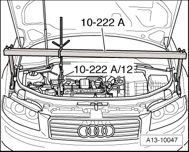
| t | Support bracket -10-222 A- |
| t | Allen key (long reach) -T10058- |
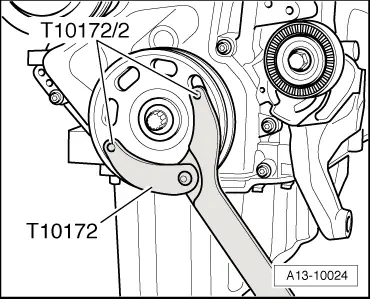
| t | Counterhold tool -T10172- |
|
|
|
|
|
|
|
|
|
|
 Caution
|
|
|
|
|
|
|
|
 Note
Note |
|
|
|
 WARNING
Note
|
|
|
|
|
|
Note
|
|
|
|
Note
Note
|
|
Note
|
|
|
|
Note
|
|
|
|
|
|
|
|
|
|
|
|
Note
|
|
|
|
|
|
|
|
|
|
|
|
|
|
|
|
|
|
|
|
| Component | Nm | |||||
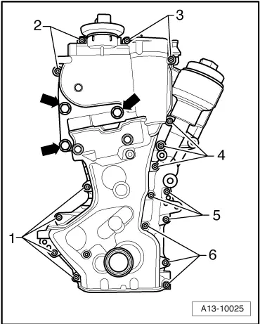
| Timing chain cover to | M6 | 10 | ||||
| cylinder block and cylinder head | M10 | 50 | ||||
| Engine lifting eye to timing chain cover | 20 | |||||
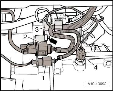
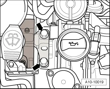
| Pressure control valve for crankcase breather system to timing chain cover | 10 | |||||
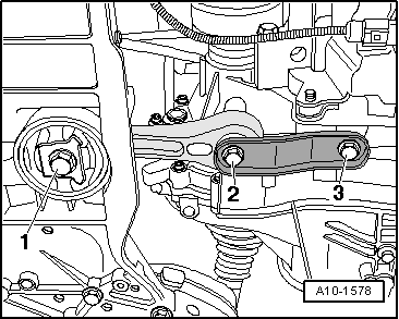
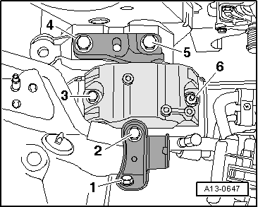
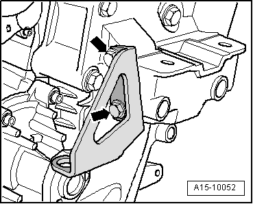
| Engine mounting to body | 50 | |||||
| Connecting bracket to engine mounting/body | 20 + 90° 1)2) | |||||
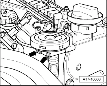
| Coolant pump pulley to coolant pump | 20 | |||||
| Idler roller to engine | 40 | |||||
| Hot air collector plate to exhaust manifold | 10 | |||||
| ||||||