
A3 Mk2
| Overview of fitting locations |
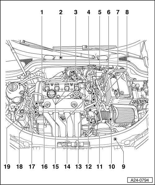
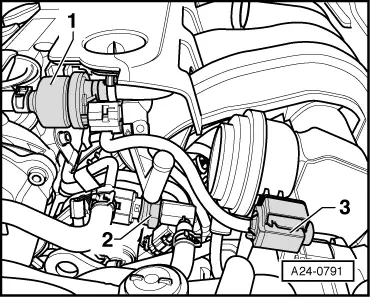
| 1 - | Activated charcoal filter solenoid valve 1 -N80- |
| 2 - | Motronic control unit -J220- |
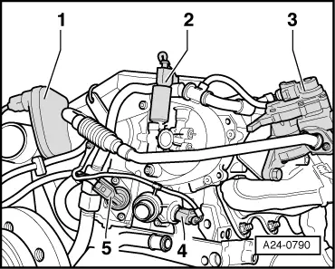
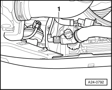
| 3 - | Exhaust gas recirculation valve -N18- with exhaust gas recirculation potentiometer -G212- |
| q | → Fig. |
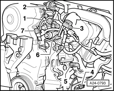
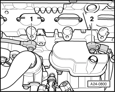
| 4 - | Camshaft control valve 1 -N205- |
| q | → Fig. |
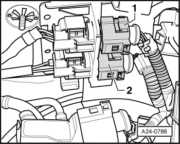
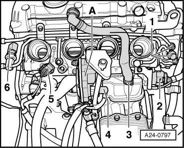
| 5 - | 6-pin connector |
| q | For Lambda probe -G39- before catalytic converter and Lambda probe heater -Z19- (black) |
| q | For Lambda probe II -G108- before catalytic converter and Lambda probe heater 2 -Z28- (brown) |
| q | → Fig. |
| 6 - | Coolant temperature sender -G62- (4-pin) |
| q | → Fig. |
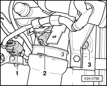
| 7 - | Fuel pressure regulating valve -N276- |
| q | → Fig. |
| 8 - | Single-plunger high-pressure pump |
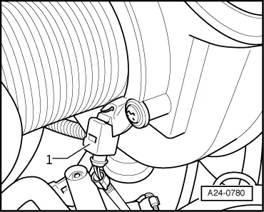
| 9 - | Coolant temperature sender - radiator outlet -G83- |
| q | → Fig. |
| 10 - | Intake air temperature sender II -G299- |
| q | → Fig. |
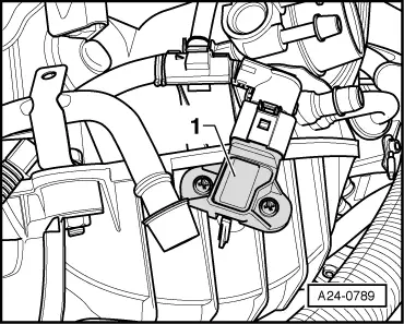
| 11 - | Intake manifold pressure sender -G71- with intake air temperature sender -G42- |
| q | → Fig. |
| 12 - | Throttle valve module -J338- |
| q | With throttle valve drive (electric power control) -G186- and angle sender 2 for throttle valve drive -G188- |
| 13 - | 8-pin connector for fuel injectors |
| 14 - | Vacuum pump |
| 15 - | Ignition coils with output stages |
| q | Ignition coil 1 with output stage -N70- |
| q | Ignition coil 2 with output stage -N127- |
| q | Ignition coil 3 with output stage -N291- |
| q | Ignition coil 4 with output stage -N292- |
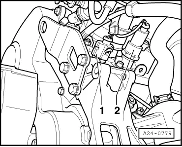
| 16 - | Fuel pressure sender -G247 |
| q | → Fig. |
| 17 - | Variable intake manifold change-over valve -N156- |
| q | → Fig. |
| 18 - | Right-side of engine (in direction of travel) |
| q | → Fig. |
| q | Fuel pressure sender, low pressure -G410- |
| q | Activated charcoal filter system solenoid valve -N80- |
| q | Variable intake manifold change-over valve -N156- |
| q | 3-pin connector for engine speed sender -G28- |
| q | Map-controlled engine cooling system thermostat -F265- |
| q | 3-pin connector for knock sensor 1 -G61- |
| q | Hall sender -G40- (camshaft position sensor) |
| 19 - | Hall sender -G40- (camshaft position sensor) |
| q | → Fig. |
|
|
|
|
|
|
|
|
|
|
|
|
|
|
|
|
|
|
|
|