
A3 Mk2
| Removing and installing camshafts |

| Special tools and workshop equipment required |
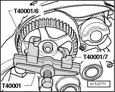
| t | Two-arm puller -T40001- |
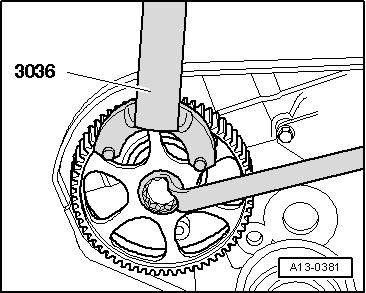
| t | Counterhold tool -3036- |
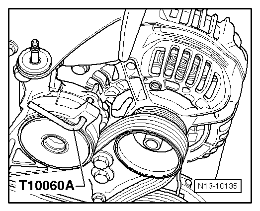
| t | Locking pin -T10060 A- |
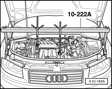
| t | Support bracket -10 - 222 A- |
| t | Thrust piece -3334- |
| t | Shackle -10 - 222 A /12- |
|
|
|
|
|
|
|
 WARNING
|
|
|
|
|
|
 Note
Note
|
|
|
|
|
|
Note
Note
|
|
|
|
|
|
|
|
Note
|
|
|
|
|
|
|
|
|
|
Note
|
|
|
|
Note
|
|
|
|
|
|
Note
|
|