audi Workshop Repair Guides

Audi Workshop Service and Repair Manuals

Pre-tensioning chain tensioner > < Removing and installing sump, engine code BVY, BVZ
Removing and installing oil pump with balance shaft assembly, engine code BVY, BVZ
Special tools and workshop equipment required
   
t  Locking pin -T10027-
Removing
–  Remove sump: engine codes BVY, BVZ → Chapter.
  W00-0719
–  Pull off chain guard. Retaining tabs can be released with a small screwdriver (insert in openings -arrows-).
  N17-0175
–  Loosen bolt on oil pump chain sprocket. Counterhold on central bolt of vibration damper.
  N17-0176
–  Use screwdriver to slacken chain rail -arrow- and lock it in position using a 3 mm Allen key -1-.
  N17-0177
–  Detach oil pump chain sprocket and disengage chain at balance shaft drive.
  N17-0178
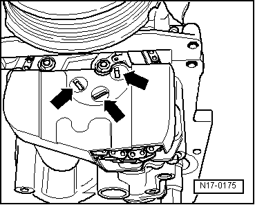
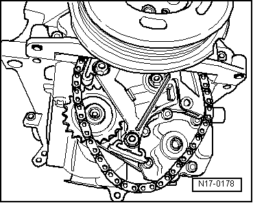
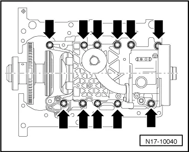
–  Loosen bolts -arrows- on balance shaft assembly, working from outside inwards, and then remove balance shaft assembly.
–  Remove intermediate plate.
Pre-tensioning chain tensioner → Chapter
Installing
t  Silicone sealant → Parts catalogue
l  
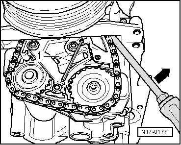
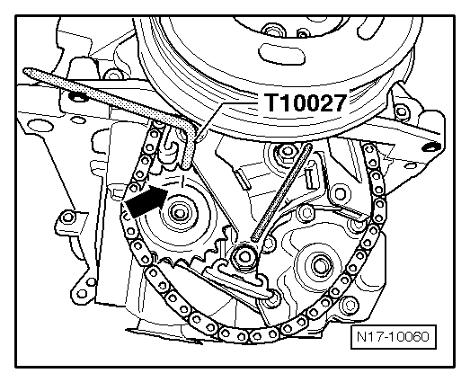
Chain tensioner must be pre-tensioned → Chapter.
  Note
t  The intermediate plate must always be renewed.
t  
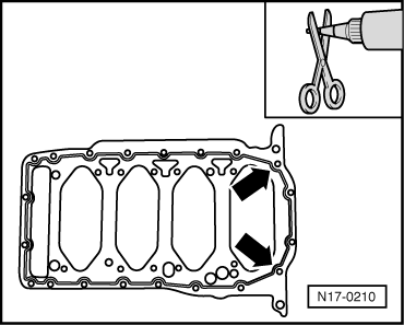
Note the use-by date of the sealant.
t  The balance shaft assembly with intermediate plate and sump must be installed and the securing bolts tightened immediately after the silicone sealant has been applied.
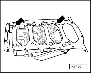
–  Remove sealant residue from cylinder block using a flat scraper.
–  Cut off tube nozzle at front marking (diameter of nozzle approx. 3 mm).
  N17-10040
–  Apply silicone sealant onto clean sealing surface of new intermediate plate as illustrated.
Note the following:
t  The bead of sealant must be 2...3 mm thick.
t  The bead of sealant must pass round the inside of the bolt holes as shown in the illustration -arrows-.
t  The bead of sealant must be applied on the cylinder block side. No sealant is required on the sump side.
  Note
The bead of sealant must not be thicker than specified, otherwise excess sealant can enter the sump and block the strainer in the oil intake pipe.
  N17-0210
–  Fit intermediate plate onto dowel sleeves on balance shaft assembly as shown -arrows-.
  N17-0211
–  Install oil pump with balance shaft assembly and intermediate plate. Tighten securing bolts -arrows- to 15 Nm + 1/4 turn (90°) further, working from inside outwards.
  Note
Note different bolt lengths → Fig..
  N17-10040
–  Turn crankshaft to TDC of No. 1 cylinder.
  A13-0076
–  Marking on chain sprocket of balance shaft -arrow- must be positioned opposite the locating hole. Use locking pin -T10027- to lock chain sprocket in this position. Place chain on chain sprocket of balance shaft.
–  Install oil pump chain sprocket and hand-tighten the bolt.
  Note
The oil pump chain sprocket can only be installed correctly in one position. When installing, you may ONLY turn the oil pump.
  N17-10060
–  Remove locking pin -T10027- and Allen key -1-. Secure oil pump chain sprocket. Counterhold on central bolt of vibration damper.
Further assembly is basically carried out in reverse order of dismantling.
Tightening torque
  N17-0177
Component Nm
Balance shaft assembly15 + 90° 1).2)
Chain sprocket to oil pump20 + 90° 1)2)
Oil pipe to balance shaft assembly10
Sump to cylinder block15
Sump to gearbox45
Oil drain plug30

l  1) 90° = a quarter of a turn
l  2) Renew nuts/bolts
   

Pre-tensioning chain tensioner > < Removing and installing sump, engine code BVY, BVZ