audi Workshop Repair Guides

Audi Workshop Service and Repair Manuals

Checking axial clearance of camshafts > < Removing and installing camshaft adjuster
Removing and installing camshafts
Special tools and workshop equipment required
   
t  Two-arm puller -T40001-
  W00-10104
t  Counterhold tool -3036-
Removing
  Note
t  Sealing surfaces at bottom of retaining frame and top of cylinder head may not be machined.
t  The camshaft bearings are integrated into the cylinder head and retaining frame. Toothed belt must be slackened before removing retaining frame.
t  Renew camshaft oil seal and sealing cap if retaining frame has been unfastened.
–  Remove cylinder head cover → Chapter.
–  Remove camshaft adjuster → Chapter.
–  Remove toothed belt → Chapter.
  W00-0270
–  Loosen camshaft sprocket using counterhold tool -3036-.
  A13-0381
–  Use puller -T40001-, claw -T40001/6- and claw -T40001/7- to pull off camshaft sprocket.
–  Detach toothed belt cover (rear) from cylinder head.
  A15-0771
–  Unscrew retaining frame bolts in the sequence -6 ... 1- and carefully remove retaining frame.
–  Remove camshafts together with drive chain from cylinder head.
–  Make sure dirt and remnants of sealant do not drop into cylinder head.
Installing
l  Tightening torques → Chapter
  Note
t  The sealing surfaces must be free of oil and grease.
t  Pistons must not be at TDC.
t  Ensure that all roller rocker fingers contact the valve ends correctly.
  N15-10103
–  Remove old sealant from groove in retaining frame and from sealing surfaces.
–  Make sure dirt and remnants of sealant do not drop into cylinder head.
–  Lubricate running surfaces of the camshafts with oil.
  N15-10105
–  Position drive chain on chain sprockets as follows (with camshafts removed):
–  Lubricate running surfaces of camshafts.
l  Cams -A- of cylinder 4 must face each other.
l  Recesses -arrows- on both camshafts must face each other.
l  The side surfaces of the recesses should be positioned exactly vertical.
–  Insert camshafts together with drive chain into cylinder head and chain tensioner.
  A15-10185
–  Check TDC position of camshafts again.
l  Cams -A- of cylinder 4 must face each other.
l  Recesses -arrows- on both camshafts must face each other.
l  The side surfaces of the recesses should be positioned in exactly vertical line to the cylinder head.
–  Lubricate running surfaces of camshafts.
  A15-10186
–  Apply an even, slightly projecting sealant bead into the clean groove of the retaining frame.
Sealant → Parts catalogue
  Note
t  Do not apply the sealant thicker than prescribed.
t  No time should be allowed to elapse when fitting and securing retaining frame, as sealant starts to harden as soon as sealing surfaces make contact.
t  Note the use-by date of the sealant.
  N15-10105
–  Fit retaining frame so that it goes past the exhaust gas recirculation valve -N18--arrow-.
–  Renew bolts for retaining frame.
–  Tighten bolts lightly in several stages, working from inside outwards.
  N15-10101
–  Tighten bolts in several stages; tightening sequence → Fig..
  Note
Take care to keep retaining frame straight.
  N15-10103
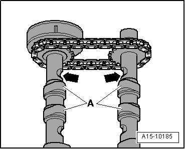
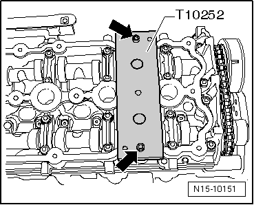
–  Then check that camshafts are in TDC position (insert camshaft clamp -T10252- as far as stop).
  Note
t  If necessary, turn camshafts slightly backwards or forwards when inserting camshaft clamp -T10252-.
t  Disregard -arrows-.
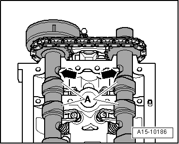
–  If it is not possible to insert camshaft clamp -T10252-, retaining frame must be removed and camshafts installed for a second time → Anchor.
–  Detach camshaft clamp -T10252-.
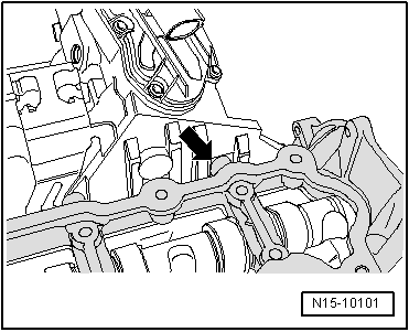
–  Drive in cap → Item approx. 1...2 mm deep using thrust piece -3334-.
–  Install camshaft oil seal → Chapter.
–  Install toothed belt cover (rear).
–  Insert parallel key into camshaft.
  N15-10151
–  Install camshaft sprocket. To tighten bolt, hold camshaft sprocket in position using counterhold tool -3036-.
  Note
t  When turning the camshaft, the pistons must not be at TDC. This could otherwise result in damage to valves and pistons.
t  Make sure parallel key is correctly seated.
–  Install toothed belt → Chapter.
–  Install camshaft adjuster → Chapter.
–  Install cylinder head cover → Chapter.
Further assembly is basically carried out in reverse order of dismantling.
  A13-0381

Checking axial clearance of camshafts > < Removing and installing camshaft adjuster