audi Workshop Repair Guides

Audi Workshop Service and Repair Manuals

Separating engine from manual gearbox > < Checking vacuum system
Removing engine
   
Removing engine
Special tools and workshop equipment required
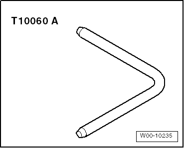
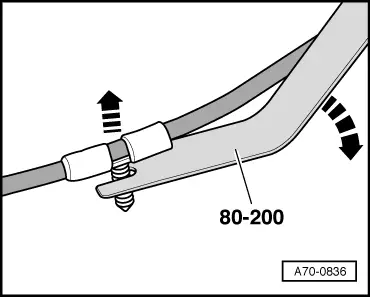
t  Removal lever -80 - 200-
t  Engine and gearbox jack -V.A.G 1383 A-
t  Stepladder -VAS 5085-
t  Drip tray for workshop hoist -VAS 6208-
t  Hose clip pliers -VAS 6362-

   
t  Hooks -2024 A /1- of lifting tackle -2024 A- for vehicles with four-wheel drive
  W00-0568
t  Locking pin -T10060 A- for vehicles with air conditioner compressor and tensioner
  W00-10235
t  Engine bracket -T10012-
t  Safety goggles
t  Protective gloves
Procedure
  Note
t  The engine is removed from underneath together with the gearbox.
t  Fit cable ties in the original positions when installing.
t  Fit heat insulation sleeves in the original positions when installing.
  W00-0598
  WARNING
Hot steam/hot coolant can escape - risk of scalding.
t  The cooling system is under pressure when the engine is hot.
t  To allow pressure to dissipate, cover filler cap on coolant expansion tank with cloth and open carefully.
–  Open filler cap on coolant expansion tank.
  A02-0061
–  Remove engine cover panel -arrows-.
  A10-11002
–  Pull cover off air duct (release clips on sides) -arrows-.
  A10-10367
–  Release clips on left and right -arrow A- and unclip air duct at bottom -2-.
–  Swivel air duct (bottom) slightly to the rear and detach air duct (bottom) from retainers -3-.
–  Detach air pipe -1- from air duct (bottom) -arrow B-.
  A10-10919
–  Unplug electrical connector -2- from air mass meter -G70-.
–  Detach hose -1-.
–  Release hose clip -3- and detach air hose.
–  Unscrew bolt -4- and remove air cleaner housing.
  A23-10236
–  Remove bolts -arrows- and detach air duct from lock carrier.
  A19-0472
  WARNING
Risk of injury as the radiator fans may start up automatically.
Even when the ignition is switched off, the radiator fans can start up without warning due to accumulated heat in the engine compartment, etc.
–  Remove bolts -top arrows- for radiator cowl.
  Note
t  The bolts -bottom arrows- are removed at a later stage.
t  Disregard -item 1-.
  A19-0473
–  Remove both front wheels.
–  Remove noise insulation -1- → Rep. gr.50.
  A10-10917
–  A3 Cabriolet: Remove noise insulation frame -arrow- → Rep. gr.50.
  A10-11037
–  Remove front left and front right wheel housing liners (front section) → Rep. gr.66.
  A10-11038
–  Release hose clip -2-, lift retaining clip -1- and remove air hose.
  A21-10051
–  Release hose clip -2-, lift retaining clip -1- and remove air hose.
–  Seal off open pipes/lines and connections with clean plugs from engine bung set -VAS 6122-.
  A21-10336
–  Unplug electrical connector -1-.
–  Remove bolts -bottom arrows- and take out air cowl downwards.
  Note
  A19-0473
Collect drained coolant in a clean container for re-use or disposal.
–  Place drip tray for workshop hoist -VAS 6208- beneath engine.
–  Lift retaining clip -arrow-, disconnect coolant hose (bottom right) from radiator and drain off coolant.
  A19-10150
–  Open hose clip -arrow-, disconnect coolant hose (bottom) leading to pump for exhaust gas recirculation cooler -V400- and drain off coolant.
  A19-10637
–  Remove bolts -bottom arrows- on rear side of radiator.
  Note
The bolts -top arrows- are removed at a later stage.
  A19-0487
–  As an additional step, open hose clip -arrow-, disconnect coolant hose at top of engine oil cooler and drain off remaining coolant.
  A19-0483
–  Remove battery → Electrical system; Rep. gr.27.
  A27-0193
–  Remove bolts -arrows- and take out battery tray -1-.
  A27-10166
–  Press release tabs and disconnect crankcase breather hose -1- from cylinder head cover.
–  Move clear vacuum hoses -arrows- at air pipe.
–  Loosen hose clip -2- and detach air pipe.
  A21-10337
–  Detach vacuum hose -2- from vacuum unit of turbocharger.
–  Disconnect vacuum hose -3-.
  Note
Disregard -item 1-.
  A21-10338
–  Detach vacuum hose from brake servo -arrow-.
  Note
  A10-10031
Place a cloth underneath heat exchanger for heater to catch escaping coolant.
–  Lift retaining clips -arrows- and disconnect coolant hoses from heat exchanger for heater.
  A10-1670
–  Detach electrical connectors -3- from bracket and unplug.
–  Move clear electrical wiring -2-3-4-5-.
  Note
Disregard -item 1-.
  A23-10003
–  Detach clamp -2-
  Note
Disregard -items 1, 3-.
  A26-10721
–  Unplug electrical connector -2- on exhaust gas pressure sensor 1 -G450-.
–  Remove bolt -3- and detach exhaust gas pressure sensor 1 -G450- from bracket -arrow-.
–  Remove top bolt -1- at bracket for particulate filter.
  Note
The installation position can vary depending on version.
  A26-10722
–  On vehicles with engine code CBEA, detach pressure differential sender -3- from cylinder head cover.
  A26-10935
–  Unplug electrical connector -4- on fuel temperature sender -G81-.
  WARNING
The fuel can become extremely hot. This can cause injuries.
t  In extreme cases the temperature of the fuel lines and the fuel can be up to 100 °C after the engine is switched off. Allow the fuel to cool down before disconnecting the lines - danger of scalding.
t  Wear protective gloves.
t  Wear safety goggles.
–  Release hose clips -2- and -3- and disconnect fuel supply hose and fuel return hose.
–  Seal off open pipes/lines and connections with clean plugs from engine bung set -VAS 6122-.
  Note
Disregard items marked -1- and -arrow-.
  A23-10169
–  Release hose clip -1- and detach coolant hose.
  Note
Ignore items marked -2- and -arrows-.
  A19-10638
–  Remove bolt -1-.
–  Push filler pipe with filler neck -2- for washer fluid reservoir to side.
  Note
t  Disregard -item 3-.
t  For illustration purposes, the installation position is shown with the fuel filter removed.
  A92-10118
–  Disengage fuel hose -2- at bracket.
–  Pull off bracket for fuel lines upwards -arrow- and move clear to one side.
–  Unplug electrical connector -1- at supplementary fuel pump -V393-.
–  Remove bolts -3-, detach bracket with supplementary fuel pump -V393- and move clear to one side.
  A23-10241
–  Release hose clip -1-, detach coolant hose from coolant expansion tank and move coolant hose clear.
  Note
Disregard -items 2, 3-.
  A10-1852
–  Lift retaining clip -arrow- and disconnect coolant hose (top left) from radiator.
  A19-10611
–  Unplug electrical connector -A- at high-pressure sender -G65--item B-.
  Note
Disregard -item C-.
  A87-10287
–  Remove bolts -top arrows- at rear and lift out radiator.
  A19-0487
–  Remove wiper arms → Electrical system; Rep. gr.92.
  A92-10125
–  Unclip washer jets -arrow-.
–  Push washer jets through assembly opening back into plenum chamber, leaving hoses connected.
  A92-0135
–  Remove seal -1-.
  Caution
Risk of damage to plenum chamber cover.
Apply a small quantity of soap solution to transition between windscreen and plenum chamber cover -2-. Then, starting at edge of windscreen, carefully pull plenum chamber cover upwards off retainer at windscreen.
–  Pull off plenum chamber cover.
  Note
  A10-1561
Use removal lever -80 - 200- to lever out the wiring clips when performing the next work steps.
  A70-0836
–  Move clear engine wiring harness at rear of plenum chamber partition panel.
–  Remove bolts -arrows- and detach plenum chamber partition panel.
  A10-1573
–  Remove engine control unit → Rep. gr.23.
–  Unplug electrical connector -1- for engine wiring harness.
  Note
Disregard -item 2-.
  A10-10018
–  Release wiring protector for engine wiring harness -arrow- and lift off.
  A10-1574
–  Open retainers for wiring duct -arrows-.
  A10-10948
–  Detach electrical connector -1- with bracket; to do so, push wheel housing liner slightly to side and release retaining wedges on back -arrows-.
–  Detach electrical connector from bracket and unplug.
  A10-11039
–  Move clear and unplug electrical connector -1-.
–  Open retainer for wiring duct -2-.
–  Remove wiring harness for engine control unit from wiring duct and place on engine.
  A10-1576
–  Unplug electrical connector -arrow- at longitudinal member (bottom left).
  Note
For illustration purposes, the installation position is shown from below.
  A10-10352
–  Slide the two clips in the direction of the -arrows- and remove cover from electronics box in engine compartment.
  A10-10349
–  Remove nut -arrow-, detach terminal 30 wire from electronics box in engine compartment and move it clear.
  A10-10633
Vehicles with manual gearbox:
–  Unplug electrical connector -1-.
  Note
Disregard -arrows-.
  A10-11093
–  Cut open cable tie -arrow- for protective cover -3-.
–  Unplug electrical connector -2-.
–  Push back protective cover and unscrew B+ cable at starter solenoid switch
–  Remove nut -1- for earth wire.
–  Remove top starter bolt.
  A27-10036
–  Detach securing clip -3- for gear selector cable from gearbox selector lever -1- and pull cable off pin -arrow-.
Metal gate relay lever:
–  Detach securing clip -4- for gate selector cable from gate relay lever -2- and pull cable off pin -arrow-.
  N34-10000
Plastic gate relay lever:
l  To prevent damage to gate selector cable, cable end-piece must be detached from gate selector cable before removing.
–  Pull locking device forwards onto stop -arrow 1- and lock by turning anti-clockwise -arrow 2-.
–  Press gate relay lever towards front -arrow 3-.
  N34-10891
Vehicles with manual gearbox (continued):
–  Remove cable support bracket -arrows- from gearbox and place to one side (selector cables remain fitted).
  A34-0621
–  Vehicles with plastic pipe between clutch master cylinder and slave cylinder: clamp off supply hose at brake fluid reservoir using hose clamp -3094-.
  A30-0127
–  Vehicles with pipe/hose assembly between clutch master cylinder and slave cylinder: clamp off hose -A- at pipe/hose assembly using hose clamp -3094-.
  Note
Disregard -arrow-.
  Note
  N34-10002
Make sure brake fluid does not come into contact with starter or gearbox when performing the following operations. If it does, clean affected area thoroughly.
–  Pull out clip -arrow- as far as stop.
–  Pull plastic pipe or pipe/hose assembly -A- out of bleeder connection for clutch slave cylinder.
  Note
Disregard -item B-.
–  Seal off open pipes/lines and connections with clean plugs from engine bung set -VAS 6122-.
  A34-10522
Vehicles with dual clutch gearbox:
–  Cut open cable tie -arrow- for protective cover -1-.
–  Unplug electrical connector -2-.
–  Push back protective cover and unscrew B+ cable at starter solenoid switch
–  Remove nut -3- and detach earth wire.
  Caution
Risk of damage to control unit (mechatronic unit) by static discharge.
Do NOT touch connector contacts in gearbox connector with your hands.
–  Touch vehicle earth with bare hands to eliminate any static charge.
–  Turn retainer catch anti-clockwise and unplug electrical connector -4- at gearbox.
  A10-10607
–  Unplug electrical connector -1-.
  Note
Disregard -arrows-.
  A10-11009
All vehicles (continued):
–  Loosen bolts -arrows- for assembly mounting (engine end) approx. 2 turns.
  N10-0437
–  Loosen bolts -arrows- for assembly mounting (gearbox end) approx. 2 turns.
  A10-1796
Vehicles with air conditioner compressor and tensioner:
  Caution
If a used belt runs in the opposite direction when it is refitted, this can cause breakage.
Before removing, mark direction of rotation of poly V-belt with chalk or felt-tip pen for re-installation.
–  To slacken poly V-belt turn tensioner in clockwise direction -arrow-.
–  Lock tensioner with locking pin -T10060 A-.
–  Take off poly V-belt.
  A13-10598
Vehicles with air conditioner compressor and tensioning roller:
  Caution
If a used belt runs in the opposite direction when it is refitted, this can cause breakage.
Before removing, mark direction of rotation of poly V-belt with chalk or felt-tip pen for re-installation.
–  Remove bolt -arrow- and detach tensioner to slacken poly V-belt.
–  Take off poly V-belt.
  A13-10796
All vehicles with air conditioner compressor (continued):
–  Unplug electrical connector -2- on air conditioner compressor regulating valve -N280-.
  Caution
Make sure that air conditioner compressor and refrigerant pipes and hoses are not damaged.
Do NOT stretch, kink or bend refrigerant lines and hoses.
–  Remove bolts -arrow-, detach air conditioner compressor -1- with refrigerant lines connected and tie up to front.
  A87-10479
All vehicles (continued):
–  Unplug electrical connector -1- at oil level and oil temperature sender -G266-.
–  Unclip bracket -2- for wire to oil level and oil temperature sender -G266- from subframe.
  A10-10025
Vehicles with front-wheel drive:
–  Remove bolts -arrows- and detach heat shield for drive shaft (right-side).
–  Unbolt drive shafts (left and right) from gearbox flange shaft.
–  Tie up drive shaft (left-side).
  A10-1633
–  Remove nuts -arrow- for coupling rod on anti-roll bar on both sides.
  A10-1141
Vehicles with four-wheel drive:
–  Remove bolts -arrows- and detach heat shield for drive shaft (right-side).
–  Detach drive shaft (left-side) from flange shaft of gearbox and tie up.
  Note
Take care not to damage the surface coating of the drive shaft.
–  Detach drive shaft (right-side) from flange shaft of bevel box.
  A34-10415
All vehicles (continued):
–  Unscrew bolts -1 ... 3- and remove pendulum support.
  A10-1578
–  Mark position of nuts -arrows- securing swivel joint.
–  Remove nuts for swivel joint (right-side).
–  If fitted, unscrew nut on bracket for front left vehicle level sender -G78-.
–  Detach swivel joint from wishbone.
  A40-0228
Vehicles with front-wheel drive:
–  Pivot drive shaft (right-side) forwards; to do so, push engine/gearbox assembly slightly forwards.
–  Tie up drive shaft to longitudinal member -arrow-.
  Note
Take care not to damage the surface coating of the drive shaft.
  A10-10028
Vehicles with four-wheel drive:
–  Swing suspension strut (right-side) outwards and support with extension -2024 A /1- as shown in illustration.
  WARNING
Accident risk from loose components of support bracket.
Secure retaining pin and swivel joint with locking pin -arrow- and nut -1-.
  Note
The illustration shows the installation position on front suspension (left-side).
  A10-10763
–  Mark position of flexible coupling and flange for bevel box in relation to each other.
–  Unbolt flexible coupling for propshaft at bevel box -arrows- (counterhold using a suitable lever at the triangular flange).
  A10-10247
–  Push engine/gearbox assembly forward slightly (towards front end) and pull propshaft off bevel box.
  Caution
Make sure not to damage the seal -arrow- in the propshaft flange.
Push the propshaft horizontally to the rear and towards the right side of vehicle as far as possible.
  Note
The propshaft must be renewed if oil seal is damaged.
  V39-1817
All vehicles (continued):
–  Remove nuts -1- and -2- and detach bracket for particulate filter.
  A26-10723
Vehicles with dual clutch gearbox:
–  Remove bolts -1- for cable support bracket.
–  Pull off securing clip -3--arrow- and remove selector lever cable from gearbox.
  Note
Disregard -item 2-.
  A37-10705
All vehicles (continued):
–  Remove bolts -arrows-.
–  Move coolant hose -3- clear.
–  Loosen hose clip -2-.
–  Unplug electrical connector -1- at charge pressure sender -G31- and detach air pipe.
  A21-10177
–  Remove bolt -arrow- and push pump for exhaust gas recirculation cooler -V400- to the side.
  Note
Disregard -items 1, 2, 3-.
  A19-10639
–  Release fasteners -arrows- and remove noise insulation -1- for sump.
  A17-10410
–  Secure engine bracket -T10012- to cylinder block with bolt -1- and nut -2- (tightening torque: approx. 20 Nm).
–  Insert engine and gearbox jack -V.A.G 1383 A- in engine support -T10012- and raise engine/gearbox assembly slightly.
  Note
  A10-1738
To unscrew bolts for assembly mounting use stepladder -VAS 5085-.
–  Remove bolts -arrows- for assembly mounting (engine end).
  N10-0437
–  Remove bolts -arrows- for assembly mounting (gearbox end).
  Note
t  Check that all hoses, pipes and wiring connections between engine, gearbox and body have been detached.
t  Carefully guide engine/gearbox assembly when lowering to avoid damage.
t  Make sure there is sufficient clearance at air conditioner compressor and at left-side drive shaft.
–  First lower engine/gearbox assembly only slightly.
–  Then swing gearbox end of engine/gearbox assembly forwards and only then lower further.
  A10-1796

Separating engine from manual gearbox > < Checking vacuum system