audi Workshop Repair Guides

Audi Workshop Service and Repair Manuals

Re-installing a used balance shaft assembly > < Removing balance shaft assembly
Installing a new balance shaft assembly
Special tools and workshop equipment required
   
t  Bits -T10099-
  W00-1175
t  Locking tool -T10255-
  W00-10250
t  
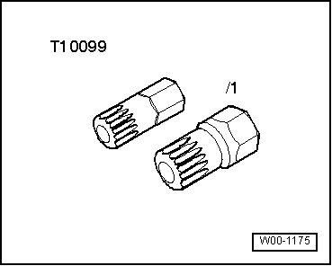
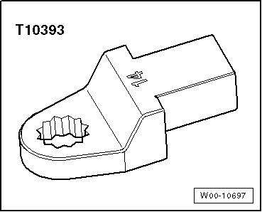
Insert tool, 14 mm -T10393-
Procedure
l  Tightening torques → Chapter „Oil pump, sump, balance shaft assembly - exploded view“
l  
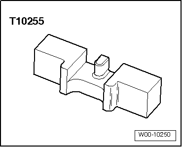
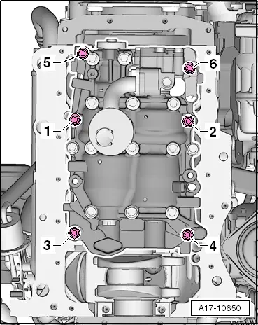
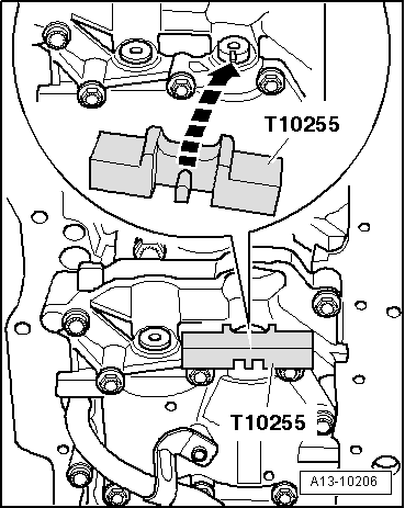
Crankshaft locked in position with crankshaft stop -T10050-.
  Note
t  
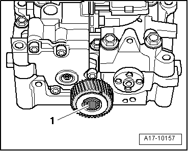
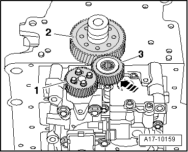
The spur gear drive of the balance shaft assembly must be installed with a specified backlash.
t  To achieve the correct backlash a coating is already applied to the new idler gear.
t  The coating is worn down rapidly and the backlash is then correct.
t  Therefore, a new balance shaft assembly must always be installed in conjunction with a new idler gear which has the correct coating.
t  
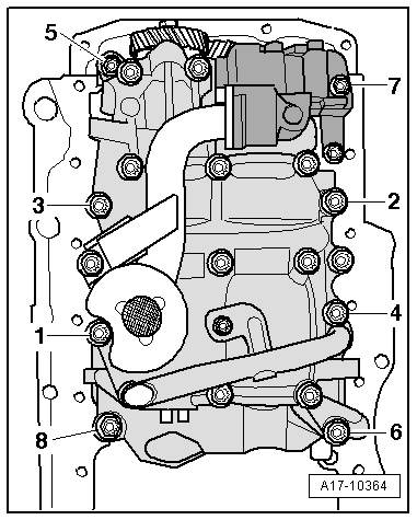
Renew the bolts tightened with specified tightening angle.
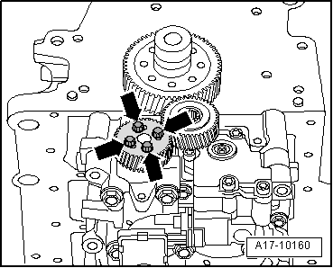
  Caution
Thrust washer can slip out of position behind idler gear.
Before positioning balance shaft assembly, slacken off bolt for idler gear as specified below, but not further. Installation position of thrust washer → Fig.
  W00-10697
–  Loosen bolt -1- for idler gear approx. 45° using e.g. bits -T10099- and insert tool, 14 mm -T10393-.
–  If not already fitted, fit dowel sleeves → Item into cylinder block for centring balance shaft assembly.
–  Attach balance shaft assembly to cylinder block.
  A17-10157
–  Balance shaft assembly with eight attachment points: Tighten bolts for balance shaft assembly → Fig..
  A17-10364
–  Balance shaft assembly with six attachment points: Tighten bolts for balance shaft assembly → Fig..
  A17-10650
–  Lock balance shaft with locking tool -T10255-, turning balance shaft as required.
l  The lug of the locking tool must engage in the groove of the balance shaft.
  A13-10206
–  Carefully fit balance shaft gear onto balance shaft; to do so, push idler gear slightly to one side.
l  Take care not to damage the coating of the idler gear.
l  The threaded holes in the balance shaft should be aligned as centrally as possible with the elongated holes in the balance shaft gear.
  Note
If it is not possible to align the elongated holes in the balance shaft gear with the threaded holes, you must turn the gear some teeth further as required and then fit it again.
–  Tighten bolts -arrows- for balance shaft gear.
–  Remove locking tool -T10255-.
  Note
  A17-10160
The following three steps have to be performed simultaneously (a second mechanic is therefore required):
–  Push idler gear -3- firmly in direction of -arrow- into teeth on spur gear -2- and balance shaft gear -1-. If necessary use a wooden rod to do so.
–  At the same time, turn balance shaft gear slightly anti-clockwise.
–  Tighten bolt securing idler gear.
–  Remove crankshaft stop -T10050-.
  Note
After installation the idler gear must have no backlash. This can be checked by exerting light pressure by hand.
Remaining installation steps are carried out in reverse sequence; note the following:
–  Install sump → Chapter.
–  Top up engine oil and check oil level → Booklet808.
–  Install vibration damper → Chapter.
  A17-10159

Re-installing a used balance shaft assembly > < Removing balance shaft assembly