audi Workshop Repair Guides

Audi Workshop Service and Repair Manuals

Charge air cooling > < Removing and installing turbocharger
Renewing vacuum unit with position sender for charge pressure positionerG581
Renewing vacuum unit with position sender for charge pressure positioner -G581-
Special tools and workshop equipment required
t  Vehicle diagnostic tester
   
t  Socket -T10422-
  W00-10847
t  Ring spanner -T10423-
  Caution
The tools listed, in particular the socket -T10422-, are only intended for use according to the procedure described in the following; do NOT use the tools for other bolted connections. There is danger of deformation if the specified torques are exceeded.
  Note
A replacement part set is available → Electronic parts catalogue for renewing the vacuum unit with position sender for charge pressure positioner -G581-.
  W00-10838
Removing
–  Remove air cleaner housing with air mass meter and connecting pipe → Rep. gr.23.
  A23-10236
–  Press release tabs and disconnect crankcase breather connecting pipe -1- from cylinder head cover.
–  Move clear vacuum hoses -arrows-.
–  Unscrew captive bolt -2-, swivel air pipe with connection to rear and detach from turbocharger.
–  Seal opening on turbocharger with sealing cap from replacement part set.
  A21-10487
–  Detach heat shield sleeve around electrical connector -1-.
–  Unplug electrical connector -1- at position sender for charge pressure positioner -G581-.
–  Detach vacuum hose -2- from vacuum unit of turbocharger.
  A21-10338
–  Depending on version, remove nut -arrow- securing oil supply line/vacuum line to cylinder head.
  N17-10165
Make an improvised tool (14 mm) to counterhold connection for oil supply line, as shown.
t  A = 110 mm
t  B = 25 mm
  Caution
It is important that you counterhold connection when loosening oil supply line. Risk of further damage occurring later.
  N21-10357
–  Counterhold connection using improvised tool and remove oil supply line -arrow- from turbocharger.
–  Seal opening for oil supply line in turbocharger with plug from replacement part kit.
  N21-10190
–  Counterhold lock nut -B- with ring spanner -T10423- and remove securing nut -A- from control rod using socket -T10422-.
  N21-10269
–  Unscrew bolts -arrows- securing vacuum unit and detach vacuum unit -A-.
Installing
  Caution
Only use new bolts and nuts from replacement part kit.
–  If necessary, remove bottom nut securing control rod from new vacuum unit.
–  Screw lock nut on control rod by hand as far as stop towards vacuum unit.
–  Guide control rod through adjusting lever on turbocharger, fit vacuum unit -A- and secure bolts.
  N21-10268
–  Tighten securing bolts -arrows- to 8 Nm.
  Note
Please ensure that guide can be moved easily on control rod.
  N21-10268
–  Remove protective cap, fit oil supply line -arrow- on turbocharger and tighten to 22 Nm.
  N21-10190
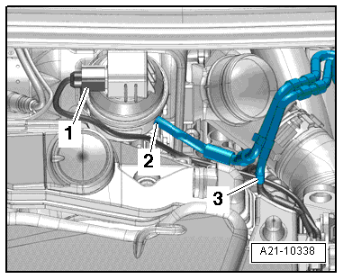
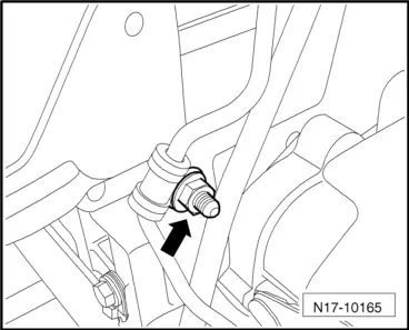
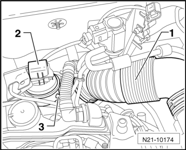
–  Plug in connector -2- at position sender for charge pressure positioner -G581- and fasten heat shield sleeve.
–  Connect vehicle diagnostic tester.
Selecting operating mode:
–  On touch screen, press button for „Vehicle self-diagnosis“.
Selecting vehicle system:
–  On touch screen, press button for „01 - Engine electronics“.
The display will show the identification and coding of the engine control unit.
Selecting diagnostic function:
–  On touch screen, press button for „011 - Measured values“.
–  On the numeric keypad, enter measured value block „120“ and confirm your entry with „Q“ key.
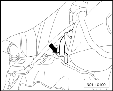
–  Connect hand vacuum pump -VAS 6213- to vacuum unit.
–  Create voltage of 0.760 V by generating a vacuum (observe minimum value of measured value block).
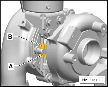
  Caution
During the following adjustment procedure for the control rod, the vacuum and the voltage of 0.760 V must be maintained.
  N21-10174
–  Slowly screw lock nut -B- for control rod downwards by hand. Adjusting lever is on bottom stop.
–  Counterhold lock nut -B- and screw securing nut -A- on control rod against adjusting lever. Tighten slightly using ring spanner -T10423-.
–  Release vacuum pressure from vacuum unit.
–  Observe minimum value of measured value block: value of 3.30 ... 3.90 V should be displayed (unpressurised).
–  Apply socket -T10422-, counterhold lock nut -B- using ring spanner -T10423- and tighten securing nut -A-.
  Caution
Create vacuum of 0.75 ± 0.05 bar for vacuum unit to ensure that adjusting lever is positioned at stop. A voltage of 0.760 V should build up.
  N21-10269
Voltage value OK
–  Press locking plate onto control rod by hand and turn by 90° in direction of -arrow-.
–  Seal connection between control rod and securing nut with sealing paint from replacement part kit.
  N21-10396
Voltage value not OK
–  Counterhold lock nut -B-, loosen securing nut -A- on control rod and adjust value by turning lock nut -B-.
–  Counterhold lock nut -B-, screw securing nut -A- in other direction and tighten connection using socket -T10422-.
  N21-10269
–  Press locking plate onto control rod by hand and turn by 90° in direction of -arrow-.
–  Seal connection between control rod and securing nut with sealing paint from replacement part kit.
  N21-10396
Continued
–  Depending on version, fit nut -arrow- securing oil supply line/vacuum line to cylinder head and tighten connection.
–  Remove sealing cap from turbocharger.
–  Fully assemble engine components.
–  Start engine and erase event memory → Vehicle diagnostic tester.
–  Check adjustment as follows:
Selecting diagnostic function:
–  On touch screen, press button for „006 - Basic setting“.
–  On the numeric keypad, enter measured value block „120“ and confirm your entry with „Q“ key.
–  On bottom half of touch screen, press button for „Activate“.
–  Observe value on bottom part of display: value should fluctuate between 0.65 ... 0.85 V and 3.30 ... 3.90 V (vacuum unit is moved to both limit stops alternately).
Voltage values OK:
–  Exit basic setting.
  N17-10165

Charge air cooling > < Removing and installing turbocharger